Shipyard Vid 1: Reinforcing the Rudder Post

Hey hey crew! As I write from La Rochelle, I have a confession to make.  I’ve been saving a treat for you!  I was holding this for when I knew we would likely be shoving offshore, so you all would have a fun video to watch as we struck out tomorrow into the notorious Bay of Biscay.  We’re planning to head out tomorrow for either a short hop to a new port or a quick shakedown and turn-around.  Either way, we’ll get water moving under the hull, learn a lot about the boat and crew’s capabilities and quirks, and hopefully make it to a new port in southern France or even Spain.  The adventure begins!  And, to celebrate the moment: a gift for you all!  Your favorite, a (drumroll please) … SHIPYARD VIDEO!  : )

I know how much you guys loooove our boat project/shipyard videos. Misery must love company, although I will say Phillip and I are far from miserable when we’re working on our boat. It beats sitting at a desk any day!  While I wrote about this project previously (Shipyard Project #1: Reinforcing Our Rudder), this will be a very fun “catch-up” video for my folks who are strictly YouTube followers as these videos will bring you up to speed on all of the very cool work and upgrades we’ve been doing on our boat this past summer while Phillip and I attempt to complete our first Atlantic Circle this winter by helping some new friends deliver their new Lagoon 42 from La Rochelle, France to the BVIs. You’ll meet Kate and Cyrus with CruiseNautic soon, a very fun, adventurous pair. I guess you have to be to willingly hop on a small boat and sail across the Atlantic, am I right?

When we finish that voyage, Phillip and I will fly home to Pensacola, work for several months and then shove off on our baby girl, the beautiful Plaintiff’s Rest, to sail her as south as possible for hurricane season next year. Likely Grenada. We are not riding out another season in the corner pocket or the Gulf. It is horrendous to see what hurricanes can do.

I’ve got several more Shipyard Videos coming over the next few weeks so you all will have some fun things to watch while we are crossing the pond. Be sure to follow along on our Facebook page (www.facebook.com/havewindwilltravel) where we will be posting via satellite through our Delorme. That way you can track us in real time across the Atlantic. Giddyup!

Shipyard Project #2: (Re)moving the Quadrant: Bonded Bolts and Other Obstacles

Maybe they should change that B.O.A.T. saying to “bonded or about to.”  I’m sure many of you have faced this.  One of the hardest parts of a boat project is the initial disassembly. Trying to get bolts that have been in place for thirty-plus years to budge.  Or how about a stainless steel bolt in an aluminum piece?  I know you’re cringing now.  But, at least I can say we had access to our curmudgeon bolt.  I had a follower post recently in order to get to bolts he needed to access to re-bed his strut, he had to remove two diesel tanks.  Just to GET TO said belligerent bolts.

Shout-out to follower, Rob Miller, who tacked that job!  Rob, you’re my hero.  In our case, with access, albeit uncomfortable and tight, to our bolts, I’ll consider us on the lucky side.  Here’s what we were dealing with.  These are the components of our rudder/steering system:

The quadrant (which is in two half-circle pieces) mounts on the rudder post by fitting onto that slotted “keyway” mentioned in the diagram, and it is then bolted together, four bolts at the base, inserted in opposite directions, which thread into opposite piece of the quadrant.  You can see here, the two bolt heads on port (your right) and the two holes that the shafts of the bolts on starboard are threaded into.

We knew in order to drop the rudder we were going to have to get these two quadrant pieces apart in order to remove the quadrant so the rudder post could be lowered.  For this reason, Phillip had the idea to spray (well, I should say Phillip had the idea to send his bendy grease monkey down in the lazarette to spray) PB Blaster on the four bolts under the quadrant periodically for a few weeks before we hauled out hoping that would help loosen those suckers.

But, as many of you know, when you allow two different metals, here stainless steel and aluminum, to sit together for years upon years, the metals can undergo a chemical reaction and literally bond themselves together.  When the boys at Perdio Sailor got in there, that is what they found.  The bolts holding our quadrant to the rudder post had thoroughly seized.

With Brandon in the starboard lazarette (which stinks, that one is super tight and uncomfortable) and Shane in the port lazarette (which is a bit more spacious, but not as much for a 265-pound guy), the boys made several attempts to get the bolts to budge.  First they tried manually.

Then with a cheater bar.  Then with the impact driver.

Then with heat (lots and lots of heat) followed by the impact driver.

Thankfully, three of the bolts finally gave up the ghost with heat and impact and came out, but we had one last stubborn holdout on the port side.  The boys continued to battle it with the impact driver, then heat, then impact, then cursing. Still nothing.  More heat, more impact, more cursing.  No movement.  Shane finally dropped his wrench and said “I’m cutting it out.”

Breaking a Bonded Bolt

I’ll be honest, I didn’t exactly know what “cut it out” meant, but watching the guys at the shipyard—who have to deal with obstacles like this every day—think through a problem and engineer a solution is the exact reason we like to haul-out with Brandon’s exceptional team and learn from their thought-processes.

Shane’s idea was to cut the bolt head off, so he could at least pull the two quadrant pieces apart and remove them from the boat.

Then he could try to drill into and perhaps extract the obstinate shaft or, if that would not work, he could drill the shaft out, enlarge all four holes slightly and either re-tap them for new bolts, or go with through-bolts instead. Shane chose the latter and we now have four bigger, stronger, more-secure bolts, locked down with Nylocs, holding our quadrant on the rudder post.

And, it was educational for Phillip and I to learn how the crew at Perdido Sailor work around, what might seem to us, an insurmountable obstacle.  You’ll also notice Shane really cleaned and spruced up our thirty-three year-old quadrant.

Thirty-three … pssssh.  That pretty gal would get carded in bars.  “Can I see your ID Ma’am?”  : )

Proof TefGel Works

In addition, to ensure this unwanted bonding did not happen again (because you never know, we might need to remove the quadrant again someday down the road), Phillip and I used TefGel during the reassembly to ensure, this time, the stainless steel bolts did not try to bond with the aluminum quadrant.

Our tiller arm served amazing proof of the power of TefGel to prevent different metals that are in contact from bonding over time.  Phillip and I installed our below-decks hydraulic auto-pilot (which we lovingly call “Lord Nelson,” because it came from a Lord Nelson boat) back in 2016 when we were hauled out to repair our rotten stringers under the mast and replace the rigging.  In order to remove the rudder from the boat, the tiller arm also had to be removed. This is the bronze tiller arm mounted above the quadrant.

And, although the arm had been in place for two years untouched, with TefGel in the mix, the stainless steel bolts that hold the bronze tiller arm on the rudder post easily unthreaded.  Proof: TefGel works people.  Use it!

Alright, one problem solved. What’s next?  Alignment of our steering cables!

Re-Aligning Our Steering Cable Pulleys

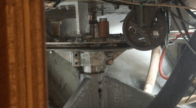
When Brandon first crawled down into our lazarette to inspect the quadrant and steering system, he noticed immediately that the alignment of our steering cable pulleys to the quadrant was not ideal.  (Even though the cables are off) can you see what Brandon saw in this photo?

The base of each steering cable pulley was about one-quarter to one-half inch lower than the “seat” (the center of the groove) in the quadrant for the cables.

This meant our cables had to travel uphill to fall into the seat of the quadrant.  Not something you want them to have to do.

It should be a perfectly-aligned straight shot from the pulley right into the seat of the quadrant.  All of these years, and I hadn’t noticed that.

Just another reason we love having professionals, like Brandon and his team, crawl all over our boat looking for potential issues.  “Look in every locker!  Check anything you want!  Sure, wiggle it. See if it works.”  I say that because we want the Perdido Sailor guys to find anything they can that needs to be fixed while we’re in the shipyard.  And I stress “need” because there is a time and money factor; no boat is going to always be in 100% pristine condition.  But, we want them to find problems while we’re in the yard, because that’s when we want to fix them—when he have great tools, supplies, and experts readily available to help and supervise, rather than finding the problem when we’re out there underway with less resources and knowledge to devote to it.

And, the joking and ribbing that goes on at the shipyard is just part of the fun.  Here, Phillip had missed the measurement of the additional height we would need to be jacked up in order to drop our rudder by just a couple of inches, and the guys never let him forget it.  If you don’t do it absolutely 100% perfect (because we all do that, all the time, right?), they’ll pick on you.  But, the more they pick on you, the more they secretly like you.  Shipyard Fact No. 64.

When Brandon saw the steering cable issue, he had the idea (since he knew we were dropping the rudder which would mean the quadrant would have to come off) to lower the quadrant just a bit to make it line up better with the pulleys.  I immediately laughed when he said it.  Just as a knee-jerk reaction, because I knew how very little room we have between the quadrant and the aft strut.  How do I know this?  Because I saw that tiny little space disappear one exhausting night in a beat-down underway when our rudder had tried to make a sneaky exit out of the boat.

That was a fun night.  And, a fun little video for you here of our quadrant literally grinding its way into the aft strut that supports the post, why it happened and what we learned the very simple remedy was: tighten the cockpit nut that threads the shaft up higher into the boat.

But, lack of space between the quadrant and the aft strut in order to properly align the quadrant with our steering cable pulleys did not hinder Brandon either.  I swear, they don’t see obstacles, they see solutions taking shape. And Brandon certainly had one here:

Cut it.  Re-engineer it.  Make it work better.  You gotta love that guy.

Brandon had his main guy, Shane, modify the aft strut by cutting a nice even chunk out of it that would allow us to mount the quadrant back on the rudder post at a lower spot to make it align perfectly with our steering cable pulleys.  Here is a video of Brandon checking Shane’s work after Shane and I reassembled the quadrant for inspection:


And, do you know what “get in there and square that up a bit” means?  Another disassembly of the quadrant by Shane and I to finalize the cut and sand it out, then reassemble the quadrant and steering cables …. again … to make sure everything worked and operated perfectly.  I’m telling you, by Day Two at the shipyard, I am quite confident I could disassemble and reassemble everything on the rudder post myself.  What an awesome confident feeling!

#diystrong

But, it will all be worth it when our quadrant now has free space and no chance of making contact with the boat if it the cockpit rudder nut gets a little loose in heavy seas (although Phillip and I now know to check and occasionally tighten that nut), and our steering cables are no longer having to step up to fall into the seat of the quadrant.  Now they are perfectly aligned.  Little things like this I’m sure will add years of awesome cruising years to our beautiful boat. And, while we continue to learn the more we work on our boat, I know she still has many lessons to teach us.  And, I know we’ll be ready to learn them, whether they occur at the yard or out in the big open blue.  It’s a great big school out there!

I know some days will look like this …

But many others will look like this …

And I wouldn’t have it any other way!  More shipyard projects to come.  Next up.  We’ll give props to the prop shaft by re-bedding the strut, replacing the cutlass bearing, and re-engineering a new coupler.  Stay tuned!

Shipyard Project #1: Reinforcing Our Rudder

Let’s talk about our rudder.  While Phillip and I are quite pleased with the majority of the systems on our boat and their original design, this was one where—if we could have been there at the factory in Ontario when the Hinterhoeller crew was putting our boat together—we would have asked them to make a slight modification to this rudder design.  Here are the components of our rudder:

It is a very sturdy, yet light-weight, high-performance rudder, with a keyway to grip the steering quadrant and a very hearty nut on the cockpit floor that turns and locks down with set screws to hold the rudder tight, the only issue we had had with it is where the rudder post penetrates the cockpit floor.  If you can imagine how much pressure is put on our rudder when we are steering down waves in a gnarly sea state, that pressure is magnified at the fulcrum point where the rudder fits through the cockpit floor.  And the only thing holding it firm there is a rudder post cap secured with three 1/4” bolts.  Here is a photo of the rudder post cap with the nut and plastic bushing, followed by one (with the plastic bushing and nut removed) and the top of the rudder post dropped down a few inches during our rudder drop.

As many of you die-hard HaveWind followers might recall, we first noticed a problem with this rudder post design during our offshore beat to windward when we sailed to Cuba in 2016.

Yep.  That’s the one.  Try to imagine how much pressure is on the rudder in that photo and how much of that was being translated to those three little bolts on the cockpit floor.  It was enough to cause our rudder post to start moving side to side, athwartship.  Which, once we saw it, immediately caused Phillip and I to go upside down in the lazarettes trying to stop it.


This is what we found when we got down there:

Just three bolts (the third, on port, is concealed behind the rudder post) with initially only one washer and one nut on each.  Adding the additional two is what Phillip and I were doing down in the lazarettes on our way to Cuba.  And, while the additional nuts did stop the majority of the athwartship movement of the rudder post on the cockpit floor during that passage, you can see in the photo above where we have tightened them so much they are literally starting to crush the cockpit floor.  This is what really worried us: such a small compromised area holding such a critical, heavy, and load-bearing component of our boat.

We knew when we got back from Cuba, we wanted to take some measures to reinforce this area before we sailed to the Bahamas.  Our initial reinforcement plan—without having to drop the rudder—was to add large stainless steel flat fender washers to help spread the load of those three bolts.  Our buddy Brandon with Perdido Sailor (with whom we usually haul-out) helped us grind the washers down to fit around the cap that sits in the cockpit floor.

Annie making an immaculate cardboard template of the area on the engine room ceiling around the rudder post.

We then used the template to make custom washers to fit around the bolts that go through the rudder post cap on the cockpit floor.

We knew this would be a temporary fix for the season, though, and that, when we got back from the Bahamas and hauled out the following year, we wanted to drop the rudder and really do this project right.  And, we knew we would be hauling out again with Brandon at Perdido Sailor because his work is exceptional and he and his guys are willing to allow us to tackle projects there ourselves while they teach, supervise, and rightfully pick on us … that’s shipyard culture.  In researching how we were going to accomplish our rudder reinforcement, I mentioned in my Post-Bahamas Projects blog what we discovered when we talked to some fellow Niagara 35 owners through the Niagara 35 Owners Facebook Group.  We found one Niagara owner, who was had just finished crossing the Atlantic, and was in the Azores at the time, not wanting to haul out and drop the rudder at the time, decided to add a very substantial backing plate around the top of the rudder post to help reinforce and secure it.

I guess you could call this a topping plate, since he mounted his on top of the cockpit floor.  After discussing this at length, Phillip and I decided we wanted to mount our plate underneath the cockpit floor for cosmetic reasons.  Either way, top or bottom, we knew a large plate mounted around this hole would help spread the very heavy load of the rudder and help reinforce the cockpit floor.  We got with our buddy Mike, who helped us configure the initial custom-washer-fix and who is a talented machinist (and owner of a beautiful 1981 Tartan 37 – boat tour HERE! – you’re welcome! : ), about making a plate for the underside of our cockpit floor.  Say “Hey!” to Mike!

And this is the wonderful piece Mike made for us!

Look at that smile.  I mean, who wouldn’t be grinning from ear to ear knowing they’re about to have a tough-as-nails rudder rig-up on the boat.  Heck yeah!

After measuring underneath the cockpit floor and assessing the sufficient space we had down there (the closest item to the rudder post is our rudder indicator on the port side), we decided on the following fix:

An 8 x 8” stainless steel 1/4” reinforcement plate 

After playing around with the plate down below in the engine room, we found sitting it in a “diamond” fashion with one corner toward the bow, one to the stern, one to starboard and one to port, would allow the plate to sit centered on the hole and not touch any other instruments on the engine room ceiling near the rudder post.  Like this:

You’ll notice those holes on the cockpit floor by the binnacle base.  Those are for the rudder post stops.  I was in the process of re-bedding them when the plate came.  We do a thousand things when we’re on the hard!

Here is the design, after the center hole in the plate was cut, mocked-up on the top of the cockpit floor:

While this fix (i.e., drilling the three necessary bolt holes through this plate and mounting it underneath the cockpit floor) seems like a pretty easy fix, Brandon spotted another issue when we were dropping and disassembling the rudder.

Pssst: This is why we love this guy and always trust him with any boat repair.

When we pulled the rudder cap from the cockpit floor this was the hole we found that was cut for our rudder post.

Does that look perfectly round to you?  Hardly.  That’s an amateur Annie cut right there!  Not something we expected to find on our blue-water Niagara, but, as the boys at the yard said, our rudder install must have been done on a Friday shift, before a long weekend.  Humans are just that.  Humans.  Someone at the Hinterhoeller facility didn’t really take their time making this cut.  But, even if it was round, Brandon also found it was about a half inch too wide for our rudder post cap.  Meaning, not only was the cap itself only secured with three 1/4” bolts, it also was not supported in this hole with solid 360-degree contact all the way around.

“We’re gonna fix that,” Brandon said, and he ingeniously came up with the idea to mount the rudder cap upside down (from the engine room ceiling up through the cockpit floor), so it would reveal the gap we needed to fill on the cockpit floor.  This photo really highlights, too, the poorly-cut hole and the gap that we wanted to fill.

Brandon then advised us to coat the cap with TefGel (that way the 610 would not stick to it) and fill that wayward-cut gap with 610.  That is what I am doing here:

Annie’s got her gun!

We then waited for the 610 to firm up enough to hold its shape (about four hours), then popped the rudder cap out and now found our hole in the cockpit floor for the rudder cap was a nice, snug fit, way more supportive than what was there previously.

This way, as Shane with Perdido Sailor explained, the hole for the rudder post cap, along with the cap and reinforcement plate will all “operate as a system” to hold the rudder secure in the hole, even with the tremendous amounts of pressure that are put on it when we are offshore.

After we sanded our 610 filling and smoothed everything up, we then bedded the rudder cap down with butyl.  Love that stuff!

We mounted the plate underneath the floor with our three bolts, using our custom washers from last year’s temporary fix and secured it all with locking nuts.  This is the complete rudder reinforcement fix:

Pretty schnazzy huh?  As Phillip said to me: “Aren’t you going to sleep better when we’re underway offshore knowing this bad boy is holding everything together?”

Yes, yes I am.

And, added bonus for you Phillip fans out there.  I snuck a video of him explaining to a boat neighbor of ours (ironically both in the slip and then at the shipyard as well!) how we discovered this problem and our thought-process in designing the reinforcement.  Enjoy!


Phillip and I are both very grateful for the help and guidance shared through the Niagara 35 Owners groups, particularly the input from Larry Dickie, as well as our buddy Mike for the machine work, and the hard-working shipyard repairmen at Perdido Sailor, who helped us engineer and accomplish this feat.  We hope sharing this fix helps some of you analyze and upgrade your own rudder systems.  As always, if you have any questions about what we did here or just want to talk about it more, feel free to comment or share!  Happy sailing folks!

And, don’t worry … we’ve got plenty more project posts to come this summer.  Here’s the (short) list!  The ones with an “A” beside them are my babies!