A Cruiser’s Wine Cellar: Article in SAIL Magazine’s 50th Anniversary Edition!

I probably had way too much fun writing this one!  Go on … ask me how many bags of wine we can stow in our “cruiser’s wine cellar!” ; )  We interrupt our regularly-scheduled Bahamas broadcast for this fun announcement!  This was such an honor and a treat for my Cruiser’s Wine Cellar piece to be included in SAIL Magazine’s 50th anniversary edition!  Wow!  This very fun article I put together at the request of Peter Nielsen with SAIL who asked for some insight into our new “creative stowage in the bilge.” A couple of custom starboard inserts afforded Phillip and I the perfect new place to keep wine cool and stable aboard s/v Plaintiff’s Rest.

 There are some fun photos of the project in the article that I hope might inspire some creative bilge stowage on your own boat!  

We hope you all enjoy the article! If you pick up a copy and enjoy it, be sure to let the folks at SAIL Magazine know. Then, tell us, where is your “cruiser’s wine cellar” on your boat? 

I love wine … Nope, still not big enough! It can never be big enough. : D

Shipyard Vid 3: New Coupling & Rot Repair

Calling all boat project fanatics, this one’s for you! Boy, did we have a time trying to get our engine aligned. While Phillip and I knew we had some kind of issue going on with our prop shaft, the key that fits in the shaft (which was always coming out and we were hammering back in, brilliant plan!), and our coupling, we didn’t know it was quite as bad as it was.

Watch along as Brandon, Shane, and the great team at http://www.perdidosailor.com help us diagnose and solve many issues relating to our prop shaft and how it seats in the transmission. We had a machinist re-engineer our old coupling and make us a new one. We also re-bedded the strut and replaced the gutless bearing.

And, just as boat projects always do, the boat had a lot of extra hidden work in store for us in the form of a rotten engine stringer portion (under the raw water pump on starboard, no surprise) that we had to repair along the way. Fun, fun! Misery loves company! Give it a watch! More photos and write-up available at http://www.havewindwilltravel.com.

I hope you all have been enjoying these shipyard videos while Phillip and I were off galavanting across the Atlantic Ocean. We’ll have plenty to share from that adventure once we get our heads back on straight.  It can be hard, at times, to transition from offshore sailors back to full-time lawyers/marketing gurus.  But, the work is always worth it.  In exchange for all of those photos and videos of us out sailing and traveling the globe, enjoy seeing us here all grimy and greasy wedged down in the engine room on our boat!  You’re welcome!  B.O.A.T., am I right?  : )

Shipyard Vid 2: Removing the Quadrant & Replacing the Cables

Maybe they should change that B.O.A.T. saying to “bonded or about to.”  The hardest part of our rudder drop was getting the stinking quadrant off! Heat, impact, cheater bars, nothing would work.  So, the creative guys at Perdido Sailor had to come up with a different fix, and boy did they!

Ahoy crew!  Shipyard Vid #2 coming at you, from Cascias, Portugal nonetheless!  I put this video together a while back so you all would have something fun to watch while we were embarking on our second Atlantic-crossing helping deliver a new Lagoon across the pond from France to the USVIs!  I know how you all LOVE boat project videos, so here’s another one for you from our interesting work at the shipyard this past summer.

While I wrote about this project several months back here, some of my followers love to see the video!  This one’s for you!  Phillip and I always enjoy working alongside the guys at the yard because we learn so much. They point out problems we didn’t even know we had and teach us fixes we didn’t even know were possible.

Watch here as we (finally!) get the quadrant off and make the necessary modifications to do that, check on our G-flexed keel seam from 2016, replace the cables for the throttle and shifter (because, according to Video Annie, they sounded like “Grandma’s panties coming down”), and shared some fun lighthearted joshing at the yard!

We hope you are all enjoying the shipyard videos and having a great time tracking us along while we are sailing back across the Atlantic Ocean. Follow on our facebook page at www.facebook.com/havewindwilltravel for real-time updates and locations via our Delorme!

Life is short. Fill your sails!

Shipyard Vid 1: Reinforcing the Rudder Post

Hey hey crew! As I write from La Rochelle, I have a confession to make.  I’ve been saving a treat for you!  I was holding this for when I knew we would likely be shoving offshore, so you all would have a fun video to watch as we struck out tomorrow into the notorious Bay of Biscay.  We’re planning to head out tomorrow for either a short hop to a new port or a quick shakedown and turn-around.  Either way, we’ll get water moving under the hull, learn a lot about the boat and crew’s capabilities and quirks, and hopefully make it to a new port in southern France or even Spain.  The adventure begins!  And, to celebrate the moment: a gift for you all!  Your favorite, a (drumroll please) … SHIPYARD VIDEO!  : )

I know how much you guys loooove our boat project/shipyard videos. Misery must love company, although I will say Phillip and I are far from miserable when we’re working on our boat. It beats sitting at a desk any day!  While I wrote about this project previously (Shipyard Project #1: Reinforcing Our Rudder), this will be a very fun “catch-up” video for my folks who are strictly YouTube followers as these videos will bring you up to speed on all of the very cool work and upgrades we’ve been doing on our boat this past summer while Phillip and I attempt to complete our first Atlantic Circle this winter by helping some new friends deliver their new Lagoon 42 from La Rochelle, France to the BVIs. You’ll meet Kate and Cyrus with CruiseNautic soon, a very fun, adventurous pair. I guess you have to be to willingly hop on a small boat and sail across the Atlantic, am I right?

When we finish that voyage, Phillip and I will fly home to Pensacola, work for several months and then shove off on our baby girl, the beautiful Plaintiff’s Rest, to sail her as south as possible for hurricane season next year. Likely Grenada. We are not riding out another season in the corner pocket or the Gulf. It is horrendous to see what hurricanes can do.

I’ve got several more Shipyard Videos coming over the next few weeks so you all will have some fun things to watch while we are crossing the pond. Be sure to follow along on our Facebook page (www.facebook.com/havewindwilltravel) where we will be posting via satellite through our Delorme. That way you can track us in real time across the Atlantic. Giddyup!

Shipyard Project No. 6: Swap to a Composting Airhead

At first, we couldn’t really get our “heads” wrapped around it, but once the system started to make sense (a simple composting unit vented to the outside), and we realized all of the nasty things we were about to remove from the boat, Phillip and I were all for it!  As you can imagine, we asked around to many, many boat owners about the pros and cons of going with a composting head, and the really far-fetched cons we heard came from boatowners who didn’t even have a composting head on their boat!  Psssshhh … 

From those owners who had swapped to a composting head (including Andy and Mia from 59-North), the only true con that was noted was the head is a bit taller and there is the occasional hard-over tack that might prevent urine from making it to the bin.  “But, in the rare event that happens,” Mia told me, “you just straighten the boat up for a minute while you do your business, and that’s that.”  Most owners with composting heads told us they were thoroughly pleased with the function and smell (which for most is non-existent, but even those who did not vent theirs told us the light mulch smell was far preferred over the previous smell of the holding tank and it’s many nasty hoses).  And, I don’t think I’ve heard of a single boat owner with a composting head going back to a manual toilet and a holding tank, which should tell you a lot.  In addition, many RV’ers raved about their composting heads, so helpful articles like this one from RV lifestyle helped to inform our decision as well.

While the install was a little tricky for us (mostly because we wanted to route the venting in a way that turned out very clean using the old channels that were designed for the propane water heater that was previously on the boat), it was really not that hard.  I did most of it on my own with little oversight.  Is it a stinky, shitty job?  Yes.  The removal, anyway.  But, it’s no worse than changing out your holding tank hoses which has to be done every so-many years, and you can take great comfort in knowing that is the last time you will ever have to experience the pleasant feel of having your hands covered in your own … stuff!  You’re welcome for that odorific memory.  That was a fun day on Plaintiff’s Rest.

Phillip and I have also been using the new composting head on the hook after our install and we are thrilled with it.  I will admit, the urine bin (we opted for the small one) is a bit small, only a gallon.  And, it turns out, after an evening of wine, that’s about equivalent to Annie’s bladder.  So, I do have to empty that bin a couple of times a day, but it’s like a 30-second chore, so no big deal.  Regarding the “mulch,” we were told each coco brick lasts about 3-4 weeks with regular use.  You can get five bricks for around $20 through Amazon.    So, the cost is roughly $4-5/month.  Each brick is about 8” long, 4” wide and 2-3” inches tall.  So, a six-month supply likely fits in the size of a milk crate.  I can assure a full year’s supply would be a mere fraction of the space our 25-gallon holding tank previously occupied.

A good friend and fellow captain and his wife (Russell and Lynn, hello!) who have used a composting head for years advised you soak one brick in one quart of fresh water overnight.  It expands to about twice its size (roughly two gallons worth of material).  Then you break it up into the composting bin and you’re set for about 3.5-4 weeks of use.  When you notice the bin has roughly exceeded its halfway point (the crank inside is a good indicator), it’s time to dump!

Phillip and I chose the Airhead because it was the right aesthetic and size for our boat, and I cannot say enough nice things about the good folks at Airhead (particularly my buddy Geoff, shout out!) who answered my many, many, literally dozens of questions.  They were very responsive and considerate (and complimentary of my install!  Thanks for the kind words Geoff!).  If you are on the fence about swapping to a composting head, feel free to send us any questions or hit up my buddy Geoff at Airhead, here is his email.  While you are considering, it is helpful to think of the many benefits we have found (that I did not anticipate when we were merely considering it) from our swap to a composting head.

Pros of Swapping to a Composting Head

  1. You no longer carry your shit along with you everywhere in a sloshing stinky tank under your bed (let’s just start there).
  2. You remove an entire electrical  system and thru-hull from the boat (the macerator for pumping overboard).
  3. You gain space and better smell quality in all lockers that contained any element of your old system (the Y-valve, the macerator, the holding tank, and all the hoses).
  4. You never have to go to the fuel dock again just to pump out.
  5. You never have to pump out again.  Yippee!
  6. You don’t have to worry about an overflow, rupture, or leak from the holding tank.
  7. You never again have to suffer through the smell of said overflow, rupture or leak from the holding tank.
  8. You’ll never again have to change out the holding tank hoses or joker valve.
  9. You’ll never again have to worry about or unclog a clogged head.
  10. Most guests will refrain from use because it freaks them out.  Yippee!
  11. No more pumping after every donation. Whon-shee, whon-shee, whon-shee.
  12. The whole boat smells so, so much better.
  13. There’s less weight aboard.  (For us this was particularly beneficial removing weight near the bow, where we work to counter-balance our heavy 200 feet of chain in the bow).
  14. We never put salt water in our old head (as we heard it contributed to smell) so we now no longer have to keep a jug of fresh water in the head for pumping.
  15. You’ll never again have to help … things … through the joker flap.  Isn’t that fun?
  16. With good aim, you’ll never again have to clean a shitty bowl.  Ever.  Yippee!

And, just in the pursuit of fairness, here are some of the cons we have heard about and/or experienced ourselves.

Cons of Swapping to a Composting Head

  1. The head is a bit taller, so the “comfort factor” of having your feet lower can play a role (it does not for me, but seems to more for men).
  2. You have to empty the urine bin often and should check it each time before you take a leak.  It sucks when it overflows (yes, we’ve already done that).
  3. Some people have told us they worry about violating some old boat regulation that requires you have a holding tank.  In the U.S., a composting head is a USCG-sanctioned Type III marine sanitation device, so you’re fine here.  With respect to other countries, as one follower said: “I would argue the composting head is a holding tank.”  Smart guy.  My lawyer brain would agree with that.  We’ve never heard of anyone ever actually being cited or otherwise penalized under this alleged old regulation.
  4. It may prove difficult to urinate on certain tacks.  (But the simple fix for this I will call the “Mia Rule” above: straighten the boat out for a minute, do your business, get back on tack).
  5. You have to find a place to dump your compost roughly once a month.  While underway, you can throw it overboard anywhere outside three nautical miles from the nearest land.  While ashore, you can (if you want the earth to get some use out of it) donate it to any garden, flowerbed, or natural earthy area, or otherwise safely dispose of it.  Simply follow local regulations and good judgment when disposing anywhere.

So, let’s dig into this already as I want to share the full details or our install and hopefully dispel any erroneous myths you all my have about composting heads.  If you may recall, this entire project emanated (ooh, great word) just as the smell did on our boat one morning when we inadvertently overflowed our holding tank.  Good times.

Here is a link to that Facebook thread if you want to read everyone’s input on swapping to a composting head.

We were on our way back from the Bahamas and, after talking to many cruisers about it, primarily Russell and Lynn, we decided no more turd tank and we added it to our Post-Bahamas Boat Projects.  But, simply deciding to explore the option does not make it possible on our boat.  We do have a rather small area in our head.  Our first obstacle in all of this was size.  Was a composting head going to fit?


After researching all three major brands (C-head, Airhead, and Nature’s Head), we found the Airhead met our needs aesthetically and size-wise.  The Airhead was a bit more stylish (I now know toilets can be stylish) than the C-head and was not quite as monstrous as the Nature’s Head.  I sent these initial photos to the folks at Airhead asking their thoughts.  Our main concern was our platform, which is approximately 12” aft, but it narrows down to only 4” going forward.  The flat area we were working with was really rather small.

Geoff at Airhead got back to me immediately and asked for more information about our space back there.  I did some more measuring and created this rough diagram for him.

Geoff, before he even knew we would be a customer, took the time to create a CAD drawing showing various configurations where he thought the Airhead, with the “hull shape” on the back (to match our slanted hull), would work.

These diagrams gave us confidence, but it was still a tough call to make because you cannot really tell whether the composting head is going to fit nicely in your head until you remove the old toilet.  But, you don’t really want to remove the old toilet until you know … It was a bit of a Catch 22.  But, we had a friend who owns a Catalina 28 (the one we helped deliver back in 2017) who had just made the decision to swap to a composting head and he let us “play around” with his (man, that sounds awful) by holding it up in our current space.

It looked do-able, so Phillip finally gave me the go.  We ordered our Airhead to have it in time while we would be in the shipyard this past summer and could do the install.  Annie’s first solo job when we hauled out was to remove the old head.

“I’m all over it!” Shipyard Annie said!

Thankfully, the old toilet was far easier to remove than I imagined.  Day One at the shipyard, even after we hauled out, dropped the rudder and removed the engine exhaust elbow, there was still a couple of hours for Annie to get this beast off.  I was thrilled to find it was only mounted with four bolts on the bottom plate and there is a hose that goes to the pump (to pull raw water into the bowl, which, like I said, we never did because we heard it contributed to smell).

And, while we, of course, pumped out entirely before we headed to the shipyard (and filled the tank with water and pumped out several times, like we always used to do when pumping out), but what we should have done was head out in the Gulf one day and run loads of water both through the toilet to the holding tank and from the holding tank out the macerator.  That would have been the smart way to do it.

I never said we were smart.  While the tank was as empty as we could get it, both the hose from the toilet to the tank and the tank to the macerator and out the thru-hull were not.  Disconnecting the toilet from the holding tank hose and working with a Shop-Vac to “contain the spill” was not a fun day for Annie at the shipyard, but damn if I didn’t get it done!

Victory!

Yes, I was that excited enough to dance with a toilet!  It was a glorious day on Plaintiff’s Rest!  To celebrate, I might need a little privacy … ; )

We’ll miss ya Jabsco … said no on ever!

The spot where the old toilet had been was stained a bit green from the rusting pump, but it cleaned up easily with the Magic Eraser.  Thank you Mr. Clean!

This was the first time I could sit the new composting head in its resting place without the old head in the way and I was confident we were going to be able to make this work!

That was an exciting day, when I could finally set her in place and see that she fit!  She fit!  She fit!  All of that worrying was done.

The Airhead was a little tall but not alarmingly so.  I was excited to get the rest of the shitty stuff off the boat and continue with the install.  Phillip and I spent a fun Saturday on the boat at the shipyard disconnecting the tank.  Our holding tank (25 gallons) sits underneath, ironically, my side of the bed, on port under our vberth.  Try to guess how many hoses were connected to the tank.

Five.  Five stinky hoses: 1) intake from the head, 2) pump-out to the deck, 3) pump-out to the macerator, 4) overflow over the side of the boat, and 5) air ventilation up at the bow.  Five hoses were pulled off the boat.  And, I’ll spare you the details, but the one down to the thru-hull was the worst.  Yuck.  Nuff said.  This here was a victorious moment on our boat!

Another victory!

The holding tank is gone!  That’s a giant Annie “Whoo! Hoo!” right there.  We also took off the macerator that day and all of the hoses.  Many of our days at the shipyard looked like this.  You eat when you can and work from sun up to sun down.

Alright, with all the crappy stuff gone, it was time to get back to the install.  Our first step was to fill the old holes on the floor with a coosa insert (where the hose to the pump came through) and 610 in the others, so we would have a solid leak-free base for our new head.


Happy worker there!  Phillip knows I love 610’ing things.

For the floor, I knew we were going to have to build a floor underneath it that would extend out to support the urine bin.  Geoff at Airhead and other composting head owners had advised the bin could not hang off on its own, it needs floor support.  I used construction paper first, then cardboard to make a template for Shane with Perdido Sailor at the shipyard to cut a nice, bevelled piece out of starboard.


Shane did a really nice job cutting the starboard.  Brandon liked to call it our “potty platform.”  Ha!

It was a perfect fit.  Although we knew we (well, I mean, I, Phillip is banned from caulking) was going to have to caulk the seams to prevent water from coming in beneath the floor piece, but it didn’t need caulk for security.  That thing was a perfect fit.

The next step was positioning the head exactly how we wanted it and mounting the brackets.


Then we could pull the protective paper off of our starboard and see what a nice clean look Shane had created for us.

Once the toilet was mounted, our next step was ventilation.  This turned out to be the trickiest part of the install for us.  Like I said, primarily because of the way we chose to run it (or hide it, I should say) in the old ventilation channel that was for the propane water heater that used to be on our boat.  We removed the water heater when we got the boat to meet insurance requirements, and we’re happy to heat our water in the kettle when we want a nice toasty below-decks spa experience!  Our water heater used to reside in what we call the “shower caddy,” a rather large (and very convenient) storage locker in our stand-up shower, which is just aft of the head.

The heater was vented through a tube along the shower wall up and out the top of the boat through the deck in what I called a “stove pipe.”  A not very pretty metal contraption, that Phillip and I have both cut many a toe-on over the years, so we were happy to see it go!  You can see it in the photo here.  Say “Hi!” to Hanna Banana.  And, yes, it was such a hideous rust-bomb we had a cover made for it to both cover it up and keep the occasional water we knew was getting into it.

We decided to replace it with a solar fan on top, which looks much better, and this would actually double-up on the ventilation, with two fans pulling the air out.

Unfortunately, when we pulled the old stovepipe off and started digging around we found a significant amount of deck rot where it had been leaking.  We knew it had, and that was the reason we had the cover made, but we didn’t know what damage it had already done.  But c’est la vie.  If you find rot, you have to fix it and stop the leak.  It made this project more tedious, but it felt good to catch a problem on the boat and remedy it before it got worse.  And, remember, I love 610’ing!

We put a tube and a half in there.  The rot extended back a good 3-4 inches on one side, 1-2 on the others.  There was a lot of digging!  But we got it filled in nicely and flushed up the seam and we were ready to install our new solar fan.  We also chose the solar fan because it creates a watertight seal to the deck.  Another biggie in the composting head install is a guarantee water will not be able to get into the system through the ventilation.  If water gets in, it messes up the composting and can lead to … I’ll just say “swampy” results.  So be sure you have a watertight seal for your ventilation to the outside, or build in a “p-trap” shape into your hose to make sure water cannot get into the composting system.


Perfect!

As I mentioned, our install was likely a bit more tedious than others because we wanted to route the ventilation system through old channels (so we would cut as few new holes as possible) and hide as much of the hose and ventilation system as possible.  In most installs, you will simply choose a place out the side of the hull or through the deck where you want the ventilation to run, cut a hole for your fan cover and run the tube to the fan.  Voila.  Airhead has some great install videos on their website here.

Notice the very visible hose going up.  It will then be connected to a fan they have mounted on the ceiling of the head where they cut through the deck and mounted a cover for the fan to vent out.

In ours, we planned to run the vent hose from the composting head through the bulkhead to the shower stall, under the shower bench (to hide the hose into the shower caddy, where we hid the fan as well), and then run through a decorative piece on the wall that previously funneled out our propane exhaust and served as a shelf in the shower for soaps, shampoo (well, not for Phillip ; ), razors, etc.  This was our plan for running the ventilation:


The hose will then run up to the fan in the shower caddy.

I’m pointing to where I planned to install the insect screen.  Airhead is adamant about this.  The screen is needed to keep insects out.  If those little buggies smell your “stuff” you are venting overboard, they’re going to be very attracted and try to find any way possible into the system.  If insects get into your composting unit, well … good luck compadre.  I hear it’s very smelly and must be dumped immediately and start again.  You must keep the insects out.  You cut the hose in an area that is easy to access and screw the male part on (the hose is self-threading which is handy) and glue the female end on.

You then check this occasionally to make sure the insect screen remains clean and clear, allowing airflow freely out but no buggies in!  This was our plan, now all we had to do was implement it.  Attaching the vent hose to the bowl was no big deal.  Just a little PVC glue and a flap to keep the hose in place and an o-ring to contain the air.  But, I’ll warn you do NOT spill that blue and purple wonder glue.  It stains instantly!

I brought Shane in to cut the hole through the wall because … well, I probably don’t need to explain that.  It’s a beautiful wooden bulkhead and hole saws are not my thing.  I always spin out of control and make an absolute mess (yes, even after I realized you have to have a pilot drill on it).  Out of the entire install, this was only the second time we brought in an expert, mainly just to make sure, aesthetically, we got the result we wanted: for both the hole through the wall and the floor plate.

I then ran the hose through to the shower caddy and began the fan install.

I did that one all on my own and I was quite proud of it.  We even ran the wire through the old propane hose (for chafe protection) back to the battery bank under our galley floor and I wired it up.  We put a fuse on it (as it will likely run for extended periods of time when we leave the boat) as well as, what I call “plug-and-play” connectors.  It was either these or a switch so we can turn the fan off at some point when we want to.  Say, when the head is empty and we will be leaving the boat for a few months.  These connectors are tucked away in the locker so an easier plug-and-play install, rather than a pretty switch, was fine with me.  This is the pic I sent Phillip when I first turned on the fan.

“This blows!” said Shipyard Annie.

The biggest monster we faced with this project was this guy!

Frankenstein!  Thankfully, we probably won’t see him again for decades (I hope) as he will be fully hidden under this piece.

But, getting him to fit and stay put was an uphill battle.  We tugged and wrestled that thing for weeks before we finally found an odd rubber PVC fitting at Home Depot that we beveled at the top to match the angle of the ceiling.

Then Brandon finally gave us the good idea to secure the weight of the PVC with zip ties.  But, making sure this beast stayed put and in the exact right position for our decorative cover I can assure was not easy and took many days of cursing and sweating in the head.  I’m not kidding.  That’s what lead to my “Can you see evidence of Annie?” in the head post!

But, we got her done!  Here is a video of me walking through the complete install:

Once installed, the Airhead folks recommend you do the “toilet paper” test to make sure the fan is in fact pulling air out of the system and overboard.

Check!  It was really cool to finally finish the project and have the new head installed.  We could tell instantly (even before using it) that the simplicity of it, omitting so many other systems (a manual pump, a macerator, a Y-valve, tanks, hoses, clogging flaps, etc.), was very appealing.  It’s just one self-contained unit that vents overboard.  That is all.  Annnnd, it allowed me to clean and paint all of those lockers that used to be smelly and avoided at all costs.  This is where our holding tank hose used to run forward to the vberth and where our Y-valve for pump out overboard or through the macerator was.  Where this once was stinky and shunned, it’s now white and fresh as a spring daisy!


This locker that I’m painting (behind the head where we keep toiletries) was where the old overflow for the holding tank ran.  We actually decided to change our sump box discharge from down the head sink to this fitting so it can now get pumped overboard and allow us to now close all sea-cocks (including the one for the head sink) when we leave the boat for extended periods.  Again, this proved to be a better use of old channels leftover from obsolete systems.  Win-win!

This was where the holding tank used to be.  It’s quite a large locker.  And where the smell used to emanate from this area anytime you simply lifted the vberth mattress, it’s now odor-free and slapped with two fresh coats of Bilgekote.  I love Bilgekote.

We built a cover for the wash-down pump in there in case things we stow in that locker go to knocking about … because that never happens on a boat, right?


We’re excited to see what we can fit in there.  Maybe the genoa?  If not Stormy McDaniels, our storm sail, for sure.  Maybe all of our paper towels and toilet paper?  And, at the very least, a shit-ton (no pun intended) of coco bricks for our many seasons in the tropics!  But now we will no longer be traveling with a turd tank and we’ll never have to pump out again.  We’re stoked!

I hope you all have enjoyed the post about our swap to a composting head.  We’ve only actually used it a couple of weekends on the boat but have been very pleased with the results so far.  I will post an update as we get about six months or so in.  But feel free to shoot many any questions you may have if you are considering making the swap, too.

And, for those who have already made the swap, inquiring minds want to know: What do you now keep in your now fresh and fragrant holding tank locker?  Do tell!

Shipyard Project No. 5: Re-Painting and Re-Insulating the Engine

This is it!  The post you all have been waiting for.  Now that the stringers under our engine are repaired, it was time to get Westie back in place and aligned so we could tackle one of the projects we were most excited about this year: PAINTING THE ENGINE!

Phillip and I have had Westerbeke-red visions dancing in our head for weeks.  The thought of having a completely leak-free (or even just less-leaky-than-before) engine that would be bright, shiny red, ready to point the finger vigorously and immediately at any leak really pops our corn.  Phillip and I were both super excited to get Westie assembled, all cleaned up, and ready for a few layers of sweet Westie red.  And, as many of you have asked us about this process (this was probably the most commented-on post from our shipyard Facebook photos), we wanted to share with you all the process in case any of you are thinking of doing the same. To be honest, this paint job, while probably one of the most visibly-rewarding of our projects this summer, was by far one of the easiest.

First, let’s talk a little about why we wanted to re-paint the engine.  While a fresh coat of paint would, as I mentioned above, greatly enhance our ability to spot and troubleshoot new leaks from the engine, I later learned this was not the primary goal.  What were we really trying to accomplish in cleaning and painting our engine?

Rust prevention.

As Brandon with Perdido Sailor explained, the number one thing to really rob years of life from your engine is corrosion and decay from rust.  Phillip and I were definitely seeing evidence of that in the layers of metal that could easily flake off of our engine, primarily on the backside where it is the greasiest and near the water pump where it suffers the most rust corrosion.  This part on our engine, the cradle support on the back, had probably suffered the worst of the rust, so Brandon devised a good plan for us to take the rust head-on and prevent further decay.

Let’s talk a little about this product: POR 15 Industrial Rust Preventer

It’s a three-step process for cleaning metal, prepping it, then painting a rust-preventative coating on it, which chemically bonds to the metal, before the final paint.  We special-ordered it from Amazon so we would receive it in time to apply to the cradle before it was time to re-assemble the engine.

That was the plan anyway.  Phillip followed the instructions to a “T” using the cleaner, then the prep, then the POR paint, followed by Westie red.  We also woke early and were at the shipyard before 6:00 a.m. that day to apply the POR before the humidity rose in the heat of the day.  Living in humid, muggy Florida, this was one downside of the product:

POR-15 is cured and strengthened by exposure to moisture and will dry faster under extreme humidity, but moderate to dry atmospheric conditions are most desirable when applying this product, because extreme humidity may cause an immediate surface cure, trapping carbon dioxide gas below the surface. When this happens, bubbling may occur. Extreme humidity at the time of application may also interfere with proper adhesion of the POR-15 coating to metal because it’s almost impossible to keep metal dry under such conditions.

Yep, you read that right.  If it’s applied in too humid of an environment, bubbling can occur.  For us, bubbling certainly did occur.

Just a few scrapes with Brandon’s knife and both the red and the POR were flaking off back to pure metal.

We’ll have to call this attempt an epic fail.

But, we’re determined sailors.  With reassembly of the engine scheduled for the next day, Shipyard Annie was sent in to try and remedy the damage to keep us on track.  It was either spend the day stripping all of the paint off of this beast manually (including the areas of mega-bonded POR that did cure properly) or—Option B—whip out this toxic devilish serum for a chemical strip:

Have any of you ever used this product?  I mean damn!  It will peel the paint off your nails.  That stuff was super intense.  But, it was our quickest option.  Phillip picked up a similar brand from the auto parts store and Annie set to it.

The minute I started slathering it onto our cradle, the paint started hissing and bubbling in violent (albeit futile) revolt!

It literally took me 12 coats of this acid with scraping in between to finally get the POR to let go.  Everyone at the shipyard said it looked like a murder scene!

It was also a little painful too.  Even through gloves, after multiple applications, the toxic aircraft paint remover began to make my hands feel cold at first, then they started in with a painful tingle.  I was honestly worried I might be unknowingly inflicting permanent nerve damage on myself.  I checked with the guys at the yard to be sure and they said it’s painful but temporary.  So, my murdering continued and finally we were back to bare clean metal for another attempt at the POR.

Brandon helped supervise this time and we applied it initially in his air-conditioned, somewhat-enclosed shop area.  (He has what I call “butcher freezer” plastic flaps that hang down, keeping the room cool for the guys but easy to come and go with tools, paints, whatever in your hands.)

Even with Brandon helping with the application we were still getting a little bubbling at the shipyard, so I took the pieces home to our fully-air-conditioned apartment for the final coat and the second time around resulted in a solid cure of the POR under the Westerbeke red.

That piece was easily the hardest part of this job.  After the cradle was in place, and the engine reassembled (with a successful alignment check by Brandon and Shane), Phillip and I were finally given the go-ahead to paint.  Say it with me: “Whoo Westie Hoo!”

Our first step was to clean the engine thoroughly with Zep.  That is some awesome de-greasing stuff.  Perfect for this situation.  Simply spraying Zep on and rinsing alone took off the majority of our oil and grease for painting.  This is the difference in the engine from merely dirty to clean.

We then scraped off any paint that was ready to jump ship.  Our goal was to get as much bare metal as we could exposed so we could start fresh with primer coats there before the final red coat.

Our next step was prep.  Shane with Perdido Sailor gave us a good tip to cover all of the hoses and wires and other fittings on the engine that we did not want painted with aluminum foil.  It was nice because it was easy to work with and would wrap around pipes and fixtures and (for the most part) just hold itself there, which made the prep work much quicker, albeit still a good three hours.  We were also careful to tape and cover caps, dipsticks, the throttle and shifter cables, the intake, etc.  When we were done, we had an odd-looking foil monster in the engine room.

Then it was time to paint.  A follower on Facebook captioned this photo Boat Project Magazine’s August Centerfold.  I’ll take that!  : )

On Brandon’s recommendation, we started with green zinc chromate on all areas that were bare metal (which were a good bit!).  The fumes were pretty intense in the engine room so we donned a mask and goggles.  A follower later recommended I probably should have thrown on a Tyvek suit for skin protection, which would probably have been much smarter.  We’re told the chemicals in that zinc chromate are pretty harsh.  If I start growing a third eyeball, I’ll let you all know.  But, you can see the green areas in the photos below.


Outside near the Perdido Sailor shop, Phillip was also painting the heat exchanger before we put it back on as well.

The next step was a grey primer over the green zinc.


The fumes were pretty intense, particularly down in the engine room.  But with a mask and goggles, the job wasn’t too bad.

Finally everything was ready for our favorite shade of red.  And, I can’t tell you how many times this awesome scene from Kinky Boots was repeated at the yard when we were getting ready to start spraying the Westie red!  I mean “Reeeeeeddddd” (with a hiss).

“Red is the color of sex!  And fear.  And danger.  And signs that say “Do not enter.”

But, all of our signs say “Yes, indeed, do paint!”  Let the Westie Red fly!

Now you see grey.  Now you don’t!

Yeah baby!  We were tickled red to pull the foil and tapes and drapes all finally away from the engine and admire her new coat.  I dare say Westerbeke red and Bilgekote grey are my new favorite color-combo.

Westie sure does look good!  Not only will we now be able to easily spot and trace all leaks of oil, water, or coolant, our engine also now has been given a few more years of rust-free health that we hope to continue.  Brandon recommended after we run the engine for 5-6 hours once we’re back in the water, which will give it time to “burn the paint off,” that we then spray the whole engine down generously with anti-corrosion to continue with our rust-prevention plan.  It will feel good to know we’re taking steps to proactively fight the rust down there.

But, one word on our prep, in case any of you are planning to paint your engines too.  We did not prep near enough.  While we did cover everything in the engine room that we did not want to be forever converted to Westerbeke red, and we did drape what I felt like were an exorbitant amount of sheets around the engine area, what we failed to do was successfully contain the red dust that fumigated from our engine room while we were painting, the entirety of which traveled all over the boat.  Read that again.

All.  Over.  The.  Boat.

Look at these photos here.  I have circled the areas that are coated with a pink dust.

When we finally pulled all of the sheets and looked around, the entire boat, going forward to the bow, had a fine layer of pink dust on it.  Thankfully—knock on a freaking jar of acetone—that stuff dries so quickly that by the time it was airborne and ready to drop, it was merely a powder that could be wiped off of the floors and acetoned off of the gelcoat.

Meaning, we did not permanently stain our entire boat pink for good.  But, we should have done a much better job of somehow “caging” the entirety of the air around the engine room.  Perhaps with more sheets taped over and above, or plastic drop cloths taped all around.  I’m just pontificating here because we sure did not contain it enough.  We probably should have had better ventilation to pull the “red air” directly out of the boat through a lazarette and draped and taped that exit hole as well.  Thankfully, while we were able to remove the red by wiping the wooden floors with a wet rag and all of the gelcoat inside the entire boat with acetone, this did not make it an easy or quick job.

The fans, in particular, took a while to clean because they pulled so much “red air” through them.

You can see in this photo the red sheen on the gelcoat.  Each section like this—particularly the sections that were textured like nonskid—took about 15 minutes to wipe clean.  We turned twenty rags red just from wiping our boat down after our poor prep job for the engine paint.

The good news is, we had planned to wipe her down regardless—bow to stern—as we always do when we have all of the soft goods out.  So, this wasn’t too much of a setback for us, but definitely an extra day of cleaning we added to our own list by not covering as much as we should have for the engine paint job.  But, lesson learned for sure.

Our engine paint project, however, did not stop with painting our engine.  We had planned from the start to also add bright LED lights in the engine room after we completed the painting and replace our old engine room insulation, for several reasons.  One, our old insulation was all rag-tag, duct-taped-on in multiple colors and always falling apart, crumbling, and making a nasty black mess every time we accessed the engine.

We primarily wanted to remove it because it was filthy.  And, two, we were sure in that crumbling condition it was not performing at its optimal heat-and-sound buffer capabilities.  We also wanted to install engine room lights so we would have excellent visibility in the engine room without having to hold flashlights in our teeth.  (Okay only Annie does that, not Phillip, but I would like to break the habit.)  The entire goal with this mini-engine overhaul was to make our engine run better, cleaner, and better enable us to work on her, troubleshoot, spot leaks, and repair issues underway.  So, cue the lights!

Phillip installed one on the front of this bulkhead over the engine, as well as on the back.

We also installed a third, larger one, that runs bow to stern, rather than athwartship, in the engine room itself behind the engine.  Phillip was sure to install them all in a way that the “on” switch can be reached from our easiest access point, the front of the engine in the galley.  I can’t show you the big one in the engine room, yet, because it will ruin the NASA insulation reveal.  Savor the intrigue!

For the insulation, we ordered four boxes of big thick rolls of Soundown insulation from the internet along with their sealing tape, and this became an exclusive Annie project.

While some of the pieces were easy to template, others were not.  These pieces under the sink were rather large, and mostly square, so I started there, with construction paper templates first, then cutting pieces out of the insulation.

This monster, though … I can’t tell you how many days at the shipyard I found (mostly legitimate) reasons to avoid starting on this wall.  With all the wires and mounts and stuff, it seemed impossible to template.  It was hard enough to rip the old insulation out of there, much less make a precise pattern to put new insulation in.

But, a project will never get done if you never start it.  So, I bucked up one morning and set to it, first with construction paper taped together to (in hopes) make the entire piece out of one template.  This was my awkward masterpiece.

I had no clue if it was actually going to squeeze in behind the small gap in the gadgets and wires I had created to work construction paper through, but Shane and I gave it a shot.  His words as it slid into perfect position: “I’m going to lose my damn job!”  : )  That was a really cool feeling for me.  Never had I done that before, but I’m confident I can now lay down engine insulation with the best of them.

But, that was just the initial “mounting” (I will call it) of the insulation to the bulkhead with the 3M 77 adhesive spray.  The tedious and very time consuming “seaming” of the insulation is what had me down in there for hours upon hours.  Shane told us the trick to keeping this insulation in good shape is to prevent any water entry into the foam.  You do this by tediously taping every exposed foam seam.  This often takes layer upon layer of tape (much link shingles) to get the tape to push the foam down, wrap, and hold.  Let’s just say I went through a lot of tape.  We also secured the insulation with screws and fender washers, and I was tickled platinum pink with the results.  Our engine room now looks like a NASA launch pad.

And, what do you see there?  Our new 21” LED light in the engine room.  Lighting up the insulation like a Christmas promenade.  It is quite the dazzling display down there now.  Westie feels like a show horse at the County Fair.  I feel bad for any drop of oil that even thinks about inkling out of our engine.  Like a prisoner trying to escape from Alcatraz, we’ll shine a spotlight on it so fast he’ll run back to where he came from and never come out again.  There will be no leaks from this engine people.  Nada.

Hope you all enjoyed the engine projects.  Guess what’s next!  Our swap to a composting Airhead.  That became a bit more of a puzzling project than we had initially anticipated.  Trust me, all of this weirdness will make sense soon!


What do you think I’m installing here?  Give it a guess!  And stay tuned!

Shipyard Project No. 4: Repair of Rotten Engine Stringer

And you thought you were going to get to paint the engine today.  Silly you!  I thought I would give you guys a flavor of just how frustrating some of these boat projects can often be.  If Phillip and I could just wake up, list one thing we wanted to accomplish on the boat that day, and actually be able to do it—just by sheer will—we’d be some might happy boat-owners.  But, no matter your will power or persistence, what you are able to get done each day on the boat is dictated entirely by what the boat has in store for you.  What’s hiding inside that project?  Maybe it’s hidden deck rot.  Maybe it’s a thirty-year bolt that’s bonded for life.  Maybe it’s a piece that breaks upon removal.  A bad design.  Faulty wiring.  Failing parts.  Only the boat knows.  And she will only tell you once you roll up your sleeves and get your hands in there.

Get in there people!

Our goal that particular day was to do exactly what you all said you wanted to see: start the engine paint project.  All that stood in the way of that lofty goal was aligning the engine first.  Typically that’s not too bad of a job. A couple of hours turning bolts and checking with feeler gauges.  “No problem,” we thought.  “We’ll be painting by noon.”

The boat had other plans.  This was one of those surprise projects we hadn’t planned for.  Projects beget projects …

You see, it’s not often a boat owner aligns his engine.  I would imagine some never find the need to do it during the course of their ownership. But, anytime you remove the prop and re-insert it, you have to realign the engine to within the tiniest thousands of degrees.  To be such a rugged, hearty engine, it does have a delicate side.  Or so I’m learning.

I’ll be honest I did not know at first what this is.  Do you?

It is an engine mount. And, while that title seems totally self-explanatory (“Ahh, they’re used to mount the engine to the boat”) I still did not know precisely what they did.  Turns out, they are adjustable.  These are precisely how you align the engine. You adjust the engine mounts with many tedious quarter turns to align the engine so the prop has a perfect straight shot to the transmission.  As many of you have noticed from our photos, some crazy nut put our engine in backwards. And, don’t worry, I’ve heard all the jokes: “You can only go forward in reverse!”  They are rather funny, but with this set-up we have two engine mounts on the forward side of the engine—one on starboard and one on port—and a single engine mount in the center of the cradle on the aft side of the engine.

You can see the engine mount here on starboard in the far left corner of the photo:

In the back, we have a cradle that supports the engine with a mount in the center:

I’ll bet you can imagine engine mounts that have been sitting undisturbed for some time don’t like it when you start shoving a wrench around their neck and trying to twist them. They respond like Oscar the Grouch. Much like the one stubborn bolt on our steering quadrant, we had one engine mount that simply would not let go. And, of course!  (Because this is how the Boat Gods show they really love you!) Luckily we had engine mount replacements for the two forward mounts, which were still serviceable but pretty far gone, the one mount we did not have a replacement for was the one that was giving us trouble.  The Aft Grouch!

Shane with Perdido Sailor tried many times to get her to budge, but she was bonded for good.  So, we were forced to order a new mount from Westerbeke (which put us behind another four days on aligning the engine).  Now, are you starting to feel me on the boat project frustration?  But we were trying to keep the optimism.

“No problem,” we thought.  “Just a small delay.”  But, when Shane started to remove the engine from the stringers and raise it up on blocks so we could install the new mounts when we had all three, this happened:

Another rotten stringer!  I mean … 

Shane was actually reluctant to tell me because he knew what we had gone through the last time we found rotten stringers on our boat.  I guess if you want to ever consider yourself lucky when you’re facing what may seem like a very bad boat problem, take comfort in that moment knowing if you ever face that problem again, you’ll know exactly how to solve it.  The easiest project to do on the boat is one you’ve done before.  Because you already know all the mistakes not to make this time around!  When Shane asked me if I wanted him and his guys to get on the rotten engine stringer repair, I said: “Nope.  I’ve got this one.”

As many of you may recall, back in 2015, Phillip and I discovered the stringers under our mast step had been rotting for some time.  Enough so that the mast was crushing its way down into the boat with a visible bump showing in the stringer just under the mast step.  This is what launched our extensive “Hard Times on the Hard” season of footage in the shipyard when we spent three months on the hill repairing our rotten stringers, replacing the rigging, and doing about a thousand other things while we were there.  That stay at the yard is what easily prepared us for this comparatively short period on the hill (only 4.5 weeks this time, as opposed to 3 months back in 2016).

Russ with Perdido Sailor and I worked side-by-side for a solid week carving all of the rot out of our stringers under the mast, cleaning and smoothing the work area, creating thick way-overbuilt coosa-board fillers and laying down 163 (yes, 163!) pieces of glass into the backbone of our boat.  She’s now stronger than ever.  If any of you have not yet seen that project, I put together a great montage video below for Brandon showcasing the repairs, or you can watch the detailed videos (Part One and Part Two) I created for our YouTube channel, or scroll through the photos below.


That was a … monster job. But one that we tackled alongside the guys at the yard.  And, Phillip and I learned a great deal about structural repairs and fiberglass work while we did it.  While it was definitely not fun or cheap, it was undeniably necessary to repair the boat and highly educational.  And, it has started to pay for itself over time.  Because you know who handled the repair of this rotten stringer portion under our engine?

Yours Truly.

While the guys at the yard were great to set me up with the right tools and supervision, it turned out to be a project I could totally handle on my own.  (Which to be honest, just felt pretty fucking cool.)  Once I started digging into the stringer, I found it, thankfully, was not rotted the entire way through—just a portion which, no surprise, laid right underneath our raw water pump.


Before we replaced our Sherwood pump with a Johnson a couple of years back, we had battled leaks from our raw water pump and rebuilt and replaced that Sherwood several times with still no luck.  We put the Johnson pump in in 2017 and haven’t had a drop down there since.  But, Sherwood had already done his damage.  However, I was pleased to find it was just a small portion of the stringer.

I will say, just like our stringers under the mast step, these stringers under the engine were not glassed on top.  This just baffles me.  So, the vertical surface where water will probably sit and where bolts will likely be drilled into—that area—you’re not going to glass.  Just the sides and leave the top as fresh, exposed wood?  While I love our boat and most of the design features, these stringers left un-sealed and exposed on the top was just not a good idea.  But, c’est la vie.  I’ve said my peace.  It is what it is.  We had rot. I had to fix it.

I showed the boys at the yard the amount of damaged wood I was able to pick and scrape away and I recommended I then cut a square portion out that we could replace with coosa inserts (much like we had done with the rotten stringers under our mast) and glass them in to build the stringer back up.  Once I got the okay, I was set to work.

The hardest part of this job (and it was a very uncomfortable four-or-so hours for me squished and sweaty down in the engine room) was cutting out the square notch. There is just not a lot of room down there and the configuration forces some very hard angles of your body and wrists in order to accomplish square cuts.  Plus, that marine plywood (when it is not compromised by rot) is some pretty dense stuff.  It took a while with a Ryobi handheld blade and an air blade saw to get it knocked out, but I did it!


I then made templates (beginning first with construction paper) for the coosa inserts.  I made Phillip cut the coosa (as payment for my services down in the engine room ; ) and they ended up being a very nice fit.


Our first step (again, much like we did with the mast step stringer inserts) was to “butter them up” as Brandon says, and glass them into place.

The next day I floated some of the gaps with 610 for a nice flush fit.

Then Brandon had the good idea to make a batch of resin and use a syringe to inject it down where the fiberglass walls of our stringers had started to pull away from the wood and then clamp them back to the wood for rigidity.  This is the port stringer, which did not have rot, but we still needed to glue the fiberglass walls back into place:

Brandon also recommended we then lay a sheet of glass over everything over to seal it all up, allowing no more water intrusion.

I will say I got some props from the boys at the yard for handling this one on my own (and on my own time, so my own dime).  I was quite pleased, as well, with how it turned out.

Shane helped us to cut and lay glass on the other stringer as well, just for added measure.

It truly is amazing he fits down there, but I can’t tell you how many times he went up and down the ladder and squeezed himself down there to do hours upon hours of work.  “Think small thoughts,” he was say, jokingly, as he made his way down.

And, very much Brandon-style, Brandon recommended (while we already in there glassing) to go ahead and add two extra supports on the front of the engine near the transmission to help keep Westie extra secure.  Do any of you know what these support beams are called?

Gussets!

I was learning something new everyday.  And, the “rounded corners” you make with resin and 406 (because fiberglass does not like 90-degree angles) are called fillets.  I’ll spare you the crazy conversation Shane and I had him trying to explain to me how to make fillets for the gussets.  I was a lost cause at first, but the boys stuck with me and dumbed things down a bit so I could pick up what they were putting down and *voila!*  It was totally worth it!

We also painted the entire area around and under the engine, including the stringers, so everything would be pristine for the re-mount.  I knew a fresh coat of Bilgekote grey would make the perfect back-drop for our bright-and-shiny Westie-red!

Next up, we paint that puppy!  Who’s excited?!

Shipyard Project No. 3: Replacing the Coupler and Cutless Bearing and Re-Bedding the Strut

Many props to our prop for hanging in there with us for so long (even though we were blind to her suffering!). We’ve been battling this problem for several years now and simply did not know what the underlying problem was. We did not know the “key” to the issue was the fact that the key kept coming out.  Here’s what we were dealing with:

Our prop shaft and coupler both have a matching notch that fits a key which helps the shaft sit tight in the coupler so it can be rotated smoothly by the transmission.  You can see the key here.

Yes, the one with the red goop all over it.  That’s Loc-tite, what we thought would be the answer to this problem.  You see, this key kept coming out.  Phillip and I are pretty diligent (we try to be, at least) about checking on our engine.  We always check the oil, transmission fluid, and coolant levels before starting.  And, if we are motoring for a significant number of hours while underway, we try to make a habit of pulling back the sink (which gives us access to our engine) and checking on Westie as he is motoring along hour after hour.

We look for oil or coolant leaks, water leaks, any loose parts, etc.  And, during our trip down to Cuba and our fantastic sails back up along the coast to Pensacola in early 2017, we noticed this key kept coming out.

Often we would find it halfway out, spinning around like a wild tea-cup ride at Disney, as the shaft was spinning.  Or, we would find it spit out about six inches forward of the transmission into the bilge. Phillip and I would start to wager bets as we would be trucking along under motor and heading down to check on the engine: “Do you think the key is halfway out by now, or already spat to the bilge?”  (Most times it was already jettisoned by the time we checked.)

Phillip and I knew this key issue was a sign that some bigger problem was likely the cause and that there was something going on that wasn’t right with our coupler or shaft.  We just did not know what.  I can’t tell you how many times we located and re-Loc-tited that sucker back in place. Dozens, if not more.

While this little key popping out might seem like a minor problem, we were worried, if it continued or worsened, the transmission could potentially lose the ability to turn the shaft.  That would be a huge problem.  So, the key was legitimately discerning.  Our first thought was to have a new key machined that stuck out a little further past the end of the shaft, with a hole drilled through it, that would allow us to run some seizing wire through it to prevent it from coming out.  That would solve the problem, right?

If that was the root problem.

As we continued cruising, to the Bahamas this past season in 2017-2018, and watching further changes occur with our prop shaft, we soon learned it was not.

Our first discovery: There’s a set screw for the key!

I’ll just have to admit, we did not know that.  For whatever reason, each time we were checking and re-hammering in this stupid little key, we just didn’t see it, or if we did, we did not know it was a set screw for the transmission key.  So, “Aha!” Moment No. 1 was making this discovery, finding the set screw had indeed rattled itself far too loose, and re-tightening him down onto the key to hold it in place.

And, of course, we goobed that guy up with red Loc-tite, too.  That seemed to be our solution for many boat problems at the time.  “Just Loc-tite it.  It’ll never come loose.”  Right, cause that’s how it works on a boat.  Nothing ever rattles.  Nothing ever breaks free.  At the time, we were using the same method with the three nuts on the back of our rudder post cap underneath the cockpit floor and you now know, from our rudder post reinforcement post, we have since come up with a better-than-Loc-tite solution there as well.

When the set screw, much like the key had, started to break free from its repeated Loc-tite baptisings and allowed the key to continue to spin out, we knew we were going to have to do something else when we hauled out in 2018.  At the time, machining a new key was the best conceivable answer.  And, in the meantime, we just continued our “locate and Loc-tite” drill to get us back from the Bahamas to Pensacola to really troubleshoot and solve this issue.

But, then something funny started happening.  Not only did the key continue to drift forward and come out.  Toward the end of our Bahamas voyage, the shaft itself began to move forward.  Yes, the shaft.  This is not the best angle, but in this photo it is sticking about an eighth to a quarter of an inch out.


This movement of the shaft itself (not just the key) prompted Phillip and I to inspect the coupler further.  We found the set screws on the coupler had also rattled themselves a bit loose, so that the coupler did not have a good tight grip on the shaft.  Phillip tightened these down.  This was during out trip back up the west coast of Florida on our way back from the Bahamas.  And, to get us back home to Pensacola so we could haul-out and investigate this further, for good measure I cinched them down with seizing wire.

At least I thought I did. Turns out I’m not the best cincher. Or maybe it would be seizer … I’m sure I’d make one helluva Ceaser!  But, knowing what I now know about how to run seizing wire (which I just learned from the boys at the yard – thanks guys!) I know this is a total useless loop.  Hell, that design probably helps both screws loosen one another …

Way to go Seizing Wire Annie.  Thumbs down.  But, I can confidently say my seizing skills have since improved after we got a custom lesson from the boys at the yard.  This is why we love working with them.  I’ll show you the trick when we get the coupler issue figured out.

Cue the haul-out!

When the boys at the yard got their hands on our boat, they noticed several things immediately that were adding to our issues with prop shaft movement.  First, they could feel and, actually with their hands alone, re-create the forward and backward movement of our prop shaft inside the coupler.  Again, not the best quality video, but it was sent to us from Shane at the yard and you can easily see the movement of the shaft in and out with just Brandon below pushing and pulling it.


This was their first cue that something far more serious was going on with our prop shaft than a loose set screw on the transmission key.  The boys could also feel that the strut had a little play in it, as they could physically move it from side to side—just a hair, but hairs can make a mess out of things offshore.  They recommended it would be best to remove, clean, and rebed the strut for a more secure fit to the boat and tighter hold on the prop shaft.

That was a fun morning I spent unbolting that guy.  Can you find the Annie in this picture:

Thankfully, I will say, almost every single part of our boat is accessible.  While it may be uncomfortable and require the talents of an inconceivable contortionist, it is reachable.  We can access, remove, and repair just about any part of our boat, because it was designed to do just that—be accessed, removed if need be, repaired if need be, and otherwise worked on!  It’s one of the very great features of our boat.  I was happy to find our four strut bolts were (with just a smidge of boat yoga) rather easily accessible right behind Westie on the engine room floor.


The shipyard guys, when they disassembled the strut, also noticed our cutless bearing was worn out.  While this surprised Phillip and I as we had replaced that cutless bearing only a few short years ago in 2014, if you consider the amount of play we had in our prop shaft, and the number of miles we put under our keel while that play was occurring, it made sense.

Lastly, when Brandon removed our coupler, he found the coupler itself was wallowed out with the movement of our shaft and it simply (tightened down its full capacity) could not get a good grip on the shaft.

When Brandon removed both the prop shaft and the coupler from the boat, he showed us the movement he could exert with his hands on the shaft.  Brandon explained the coupler should slide on and have an absolute snug fit with no movement.  He and Shane also said we were lucky the shaft was going forward.  This happened when we were in forward gear because the propeller is trying to work itself forward through the water.  If we had backed down hard enough in reverse, the prop would have been working to move itself backwards through the water and could have worked its way right out of the boat with the condition our coupler was in.  Now, I have a new boat nightmare.  Thanks boys.

Here is a video of Brandon showing us the movement in the coupler and having fun at my expense. You will be surprised by the play in our coupler.  You can hear it audibly in the video.  You’ll also enjoy Brandon’s response to my joking that he had “purchase discretion up to $800.”  “Oh, it’s $799 then.  $799!”  Gotta love those guys at the yard.


So, with this revelation, we were in for a re-bedding of the strut, a new cutless bearing, and a new coupler.  But, if we were going to replace the coupler, we wanted to re-engineer it so the coupler would not allow the key to come loose or the shaft to try to move forward again after the many more miles we plan to put on our boat.  For this reason, Brandon hired a local machinist to create a cap that bolts onto the end of our coupler to hold the shaft in place. He kept a window hole in the cap so we could see the shaft and visibly confirm its location in the coupler.  The machinist also included a threaded hole in the center that we could use to twist a bolt down to pop the shaft out if it had, for whatever reason, seized up in the coupler.  Overall, it was a better, stronger design for our boat and eliminated all movement in our prop shaft.  Here is the new coupler!

And, fun little lesson for all you boat project fanatics today.  Notice Shane’s method for fastening seizing wire in the photo above. While everyone can do it differently, I definitely liked his idea of purposefully routing the wire in a way where one bolt’s attempt to unthread and turn to the left would result in a tug on the other bolt toward the right, and vice versa.  Meaning, as the bolts try to loosen themselves they are, in fact, tightening one another.  Thanks Shane!

Little things like this can make all the difference out there on a two-week passage where you are working all systems so hard twenty-four hours a day.  Phillip and I know we will sleep better and have more peace of mind knowing this system, too—our prop shaft, the coupler, the cutless bearing, and the strut—have all been inspected, re-mounted, secured, or re-engineered to be stronger and more stable for our rough passages.

This is the reason Phillip and I decided to devote the time and money this summer to haul-out and do these “mission critical” repairs and upgrades as we have some big cruising plans this fall.  And, some big destinations to announce!  We can’t wait to share our plans with you (you know, the ones written in sand at low tide ; ).  But, next up, we’ve got some more cool shipyard projects to share with you.  Hope you all are enjoying our boat labor this summer!  You get to pick next week’s topic.  Because:

I can’t make heads …

… or tails of it!

Would you like to see our swap to the composting head or re-painting of our Westerbeke engine.  You decide.  Leave your vote in a comment below!

Shipyard Project #1: Reinforcing Our Rudder

Let’s talk about our rudder.  While Phillip and I are quite pleased with the majority of the systems on our boat and their original design, this was one where—if we could have been there at the factory in Ontario when the Hinterhoeller crew was putting our boat together—we would have asked them to make a slight modification to this rudder design.  Here are the components of our rudder:

It is a very sturdy, yet light-weight, high-performance rudder, with a keyway to grip the steering quadrant and a very hearty nut on the cockpit floor that turns and locks down with set screws to hold the rudder tight, the only issue we had had with it is where the rudder post penetrates the cockpit floor.  If you can imagine how much pressure is put on our rudder when we are steering down waves in a gnarly sea state, that pressure is magnified at the fulcrum point where the rudder fits through the cockpit floor.  And the only thing holding it firm there is a rudder post cap secured with three 1/4” bolts.  Here is a photo of the rudder post cap with the nut and plastic bushing, followed by one (with the plastic bushing and nut removed) and the top of the rudder post dropped down a few inches during our rudder drop.

As many of you die-hard HaveWind followers might recall, we first noticed a problem with this rudder post design during our offshore beat to windward when we sailed to Cuba in 2016.

Yep.  That’s the one.  Try to imagine how much pressure is on the rudder in that photo and how much of that was being translated to those three little bolts on the cockpit floor.  It was enough to cause our rudder post to start moving side to side, athwartship.  Which, once we saw it, immediately caused Phillip and I to go upside down in the lazarettes trying to stop it.


This is what we found when we got down there:

Just three bolts (the third, on port, is concealed behind the rudder post) with initially only one washer and one nut on each.  Adding the additional two is what Phillip and I were doing down in the lazarettes on our way to Cuba.  And, while the additional nuts did stop the majority of the athwartship movement of the rudder post on the cockpit floor during that passage, you can see in the photo above where we have tightened them so much they are literally starting to crush the cockpit floor.  This is what really worried us: such a small compromised area holding such a critical, heavy, and load-bearing component of our boat.

We knew when we got back from Cuba, we wanted to take some measures to reinforce this area before we sailed to the Bahamas.  Our initial reinforcement plan—without having to drop the rudder—was to add large stainless steel flat fender washers to help spread the load of those three bolts.  Our buddy Brandon with Perdido Sailor (with whom we usually haul-out) helped us grind the washers down to fit around the cap that sits in the cockpit floor.

Annie making an immaculate cardboard template of the area on the engine room ceiling around the rudder post.

We then used the template to make custom washers to fit around the bolts that go through the rudder post cap on the cockpit floor.

We knew this would be a temporary fix for the season, though, and that, when we got back from the Bahamas and hauled out the following year, we wanted to drop the rudder and really do this project right.  And, we knew we would be hauling out again with Brandon at Perdido Sailor because his work is exceptional and he and his guys are willing to allow us to tackle projects there ourselves while they teach, supervise, and rightfully pick on us … that’s shipyard culture.  In researching how we were going to accomplish our rudder reinforcement, I mentioned in my Post-Bahamas Projects blog what we discovered when we talked to some fellow Niagara 35 owners through the Niagara 35 Owners Facebook Group.  We found one Niagara owner, who was had just finished crossing the Atlantic, and was in the Azores at the time, not wanting to haul out and drop the rudder at the time, decided to add a very substantial backing plate around the top of the rudder post to help reinforce and secure it.

I guess you could call this a topping plate, since he mounted his on top of the cockpit floor.  After discussing this at length, Phillip and I decided we wanted to mount our plate underneath the cockpit floor for cosmetic reasons.  Either way, top or bottom, we knew a large plate mounted around this hole would help spread the very heavy load of the rudder and help reinforce the cockpit floor.  We got with our buddy Mike, who helped us configure the initial custom-washer-fix and who is a talented machinist (and owner of a beautiful 1981 Tartan 37 – boat tour HERE! – you’re welcome! : ), about making a plate for the underside of our cockpit floor.  Say “Hey!” to Mike!

And this is the wonderful piece Mike made for us!

Look at that smile.  I mean, who wouldn’t be grinning from ear to ear knowing they’re about to have a tough-as-nails rudder rig-up on the boat.  Heck yeah!

After measuring underneath the cockpit floor and assessing the sufficient space we had down there (the closest item to the rudder post is our rudder indicator on the port side), we decided on the following fix:

An 8 x 8” stainless steel 1/4” reinforcement plate 

After playing around with the plate down below in the engine room, we found sitting it in a “diamond” fashion with one corner toward the bow, one to the stern, one to starboard and one to port, would allow the plate to sit centered on the hole and not touch any other instruments on the engine room ceiling near the rudder post.  Like this:

You’ll notice those holes on the cockpit floor by the binnacle base.  Those are for the rudder post stops.  I was in the process of re-bedding them when the plate came.  We do a thousand things when we’re on the hard!

Here is the design, after the center hole in the plate was cut, mocked-up on the top of the cockpit floor:

While this fix (i.e., drilling the three necessary bolt holes through this plate and mounting it underneath the cockpit floor) seems like a pretty easy fix, Brandon spotted another issue when we were dropping and disassembling the rudder.

Pssst: This is why we love this guy and always trust him with any boat repair.

When we pulled the rudder cap from the cockpit floor this was the hole we found that was cut for our rudder post.

Does that look perfectly round to you?  Hardly.  That’s an amateur Annie cut right there!  Not something we expected to find on our blue-water Niagara, but, as the boys at the yard said, our rudder install must have been done on a Friday shift, before a long weekend.  Humans are just that.  Humans.  Someone at the Hinterhoeller facility didn’t really take their time making this cut.  But, even if it was round, Brandon also found it was about a half inch too wide for our rudder post cap.  Meaning, not only was the cap itself only secured with three 1/4” bolts, it also was not supported in this hole with solid 360-degree contact all the way around.

“We’re gonna fix that,” Brandon said, and he ingeniously came up with the idea to mount the rudder cap upside down (from the engine room ceiling up through the cockpit floor), so it would reveal the gap we needed to fill on the cockpit floor.  This photo really highlights, too, the poorly-cut hole and the gap that we wanted to fill.

Brandon then advised us to coat the cap with TefGel (that way the 610 would not stick to it) and fill that wayward-cut gap with 610.  That is what I am doing here:

Annie’s got her gun!

We then waited for the 610 to firm up enough to hold its shape (about four hours), then popped the rudder cap out and now found our hole in the cockpit floor for the rudder cap was a nice, snug fit, way more supportive than what was there previously.

This way, as Shane with Perdido Sailor explained, the hole for the rudder post cap, along with the cap and reinforcement plate will all “operate as a system” to hold the rudder secure in the hole, even with the tremendous amounts of pressure that are put on it when we are offshore.

After we sanded our 610 filling and smoothed everything up, we then bedded the rudder cap down with butyl.  Love that stuff!

We mounted the plate underneath the floor with our three bolts, using our custom washers from last year’s temporary fix and secured it all with locking nuts.  This is the complete rudder reinforcement fix:

Pretty schnazzy huh?  As Phillip said to me: “Aren’t you going to sleep better when we’re underway offshore knowing this bad boy is holding everything together?”

Yes, yes I am.

And, added bonus for you Phillip fans out there.  I snuck a video of him explaining to a boat neighbor of ours (ironically both in the slip and then at the shipyard as well!) how we discovered this problem and our thought-process in designing the reinforcement.  Enjoy!


Phillip and I are both very grateful for the help and guidance shared through the Niagara 35 Owners groups, particularly the input from Larry Dickie, as well as our buddy Mike for the machine work, and the hard-working shipyard repairmen at Perdido Sailor, who helped us engineer and accomplish this feat.  We hope sharing this fix helps some of you analyze and upgrade your own rudder systems.  As always, if you have any questions about what we did here or just want to talk about it more, feel free to comment or share!  Happy sailing folks!

And, don’t worry … we’ve got plenty more project posts to come this summer.  Here’s the (short) list!  The ones with an “A” beside them are my babies!

Post-Bahamas Boat Projects (We’re Dropping the Rudder!)

Schadenfreude.  I know it’s German, but I have no idea how to say it.  A good friend of ours taught it to us when he was telling us what great pleasure he took in seeing Phillip and I knee-deep in boat projects instead of wading in crystal green waters, cocktail in hand.  “Somehow I like the idea of you two working hard instead of playing in the Bahamas.  That must be the German side in me coming out.  And, did you know that Germans are the only culture that has a word to express joy in another’s discomfort or pain?  Schadenfreude.  Says a lot about the culture doesn’t it?”  He’s a funny guy, that one.  So, for Conrad and all the other brutal Germans out there who would take great schadenfreude in our boat project phase, this one is for you. Misery loves company!  Although I wouldn’t say Phillip and I are anything near miserable when we’re doing boat projects.  Seriously!  We’re usually smiling most of the time.  I know.  We’re those people.  Don’t you just hate those people?

We don’t!  We are those people!

Ahoy followers!  Following our awesome voyage to the Bahamas this past season, Phillip and I definitely (as we always do) racked up a pretty extensive list of boat projects to tackle when we got home.  Some were necessary repairs that we had been watching for a while and knew we finally needed to get serious about (think hauling out and dropping the rudder).  Joy.  Others are just for cosmetic or comfort reasons—some inspired by our cruising this past season—but we’re eager to get on those just the same.

And, if you’re starting to think we might just have a bit of a falling-apart boat because we sure spend a lot of time every year doing boat projects and maintenance, we’ll I’d have to say you’re just crazy.  Plumb cRaZy.  Boats require a ton of maintenance and upkeep.  Even ones (well, I should say especially ones) in great condition.  It took a lot of work, time, and sweat to prepare our boat this past year to take us comfortably to the Bahamas, but it was all totally worth it.  Phillip and I feel privileged and lucky to own such a fantastic, old blue-water boat that we’re honored to get to work on her.  At least that’s the word we use when we’re stinking, hot, sweaty, and cramped into some ridiculously-uncomfortable places while working on her.  “I’m sure honored to be here pretty gal,” I will whisper.  But our Niagara has definitely earned all of our spare time and money each time she cranks right up, pops out her sails, and whisks us away to another fabulous distant shore, usually steering the entire time all by herself.

With plans this coming season to likely head back to the Bahamas to truly enjoy the Exumas, which we did not have time to explore this past winter, Phillip and I are eager to dig our teeth into this summer’s list and get it knocked out so we can start the long and arduous process of provisioning and packing for our next adventure.  Hooray!  Who’s on board?  Let’s get this party started already!  Here is the actual (always growing) list:

Project No. 1: The Rudder

That’s a pretty important part of the boat, right?  Next to hull integrity, a sturdy keel, along with solid rigging and sails, the rudder is one of the only things that, without it, the boat simply cannot go.  In fact, without it, the boat might easily sink.  I have to admit that’s one of the things I really dislike about the rudder.  Its cruciality to both the ability of the boat to both navigate and remain bouyant makes it almost too connected and powerful.  Like a frenemy.

If you recall, we first noticed an issue with our rudder during our voyage to Cuba.

Yeah, that passage.  Bashing our way to windward for five days.  That was fun.  (Okay, it was, actually, but it was exhausting, too, and very hard on the boat.)  That much heel and that much wind puts a lot of pressure on the rudder and, after a few days of it, we started to notice some athwartship movement in our rudder.  I know what you’re thinking.  That’s not a part you want to see movement in.  It makes me think of the keel and how gut-wrenching it might be to watch it bend, even just slightly, from starboard to port as we heel over.  Uggh.  That seriously gives me goosebumps.  Unfortunately, that’s what we were noticing.  Each time the boat would heel with a gust of wind and climb to weather, the top of the rudder post in the cockpit would move about a quarter to a half inch from port to starboard.  We had a Rudder on the Loose!

Phillip and I both spent a good part of that voyage hanging upside down in each of the lazarettos adding extra nuts to the three bolts that hold our rudder cap in place on the cockpit floor.

For this reason, one of the projects on our list last summer while we were preparing to travel to the Bahamas was an interim reinforcement of our rudder by fitting some extra wide fender washers on the three bolts that hold our rudder cap in place.


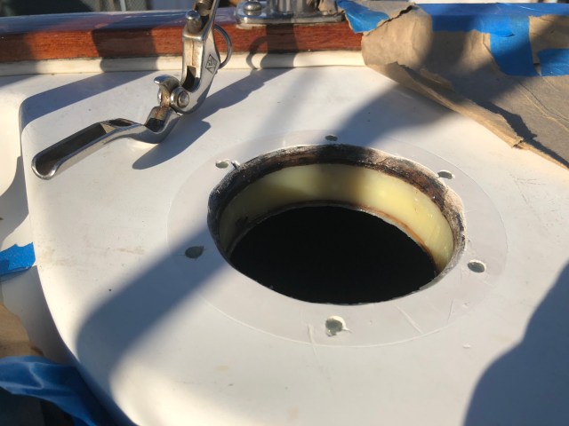
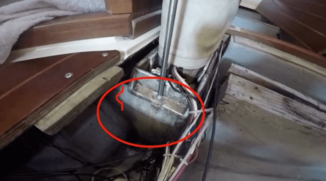
We knew this would be a temporary fix for the season, though, and that, when we hauled out the following year, we wanted to drop the rudder and really do this project right.  After doing some research (which we are always thankful for the helpful and insightful fellow Niagara 35 owners on the Niagara 35 Owners Facebook Group who share lessons learned from projects like this) we found other owners head dealt with this play in the rudder as well and decided to reinforce the backing for the rudder cap on the cockpit floor.  It really is a sh&*-ton of pressure to all culminate at one very small round hole on the cockpit floor, secured by three small bolts.  For this reason, you will see in the photo below, one Niagara owner decided to add a very substantial backing plate around the top of the rudder post to help reinforce and secure it.

Meet Larry Dickie!  Ironically named after my own people, the infamous Alabama Dickeys (albeit a slightly different spelling).  After Larry posted this photo and a brief write-up about the project, we reached out to him and he proved to be a treasure-trove of information for this particular project and many, many others.  Here is what Larry had to say:

Larry Dickie‎ Niagara 35 Owners Group

January 26 near Horta, Portugal ·

“A couple of days ago I posted pics from the N35 rudder rebuild I did. I neglected to add this critical piece, applicable to all versions of Niagara (IMHO).  The area in the cockpit flooring is, where the top of the rudder post exits, simply not strong enough to take the very severe and continual torque associated with long passages (or possibly even much shorter passages). I had been warned about this by another N35 owner, years ago. But this repair/upgrade somehow fell off the hundred-job list before we departed. Even though I had placed straight thickened epoxy for several inches around the area when I recored the sole, it was still not strong enough. A few days off Horta, during a dismal night watch, I noticed the top of the rudder post moving slightly as we came off each wave – boy, not a good feeling in the pit of my stomach there.

Now, let me be the first to admit this is not the prettiest fix. But in the Azores, you can only really get good boat work assistance in Horta (Mid-Atlantic Yacht Services). They made this plate for me, as per my napkin drawing; it was based on the fact that there was limited space undernearth to place thru-bolts. Yes, those hex-bolts are not the prettiest, but all that was available. If back in Canada, I would most likely have buried this whole plate within the sole and epoxied over it. All things considered, I’m more than happy with the end result – top end of the rudder now does move at all, even in heavy seas.
All this to say to other N35 owners who are, or contemplating heading off: shore-up the rudder post at the top end (assuming many of you already have).”


Did you note Larry’s location when he posted that?  Horta, Portugal!  That’s right.  The Azores.  Those magic islands Phillip and I were exceedingly lucky enough to be able to visit and enjoy during our Atlantic-crossing with Yannick.  There is something special about that place, I tell you.  Something indescribable.

We certainly plan to sail our boat across the Atlantic someday, stopping at both Bermuda and the Azores again, so it was nice to see another Niagara 35 making the trip.  Larry was very generous to share his experience with this issue with us and his extensive upgrade.  When we haul-out this summer, we plan to drop the rudder and install a similar wide backing plate in the cockpit floor, likely glassed in, to reinforce and further support the rudder post, particularly at the potential pivot point here where it is secured at the cockpit floor.  Our buddy Brandon with Perdido Sailor, Inc. also advised us he has seen this issue before where the rudder post also actually becomes worn down from use and is not as tight in the bushing, allowing for play.  If he finds that is the case with our rudder, he recommended we add a thin layer of epoxy along the post to literally “widen” it back up so that it is a snug fit in the bushing preventing movement.  This will be an extensive project. Likely our most complicated and costly of the summer.  But we never want to see movement in the rudder post again.  That is a very frightening thought when your boat is pitching and tossing, trying to hold course in heavy seas.  Stay tuned.

Project No. 2: Prop Shaft Key

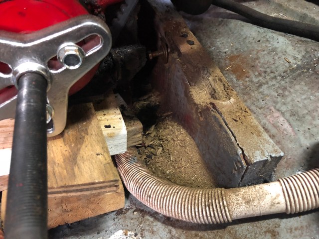
This is key.  We’ve been battling this guy for a while.  And, I have to laugh because at times I have to really feel sorry for our boat.  It’s like she tries and tries to gently show us there’s a problem.  She wiggle a nut loose, squeeze out a few drops of fluid, or let out a repetitive thud, thud, thud which should translate to “look here,” “hey, check this out,” or “I need tightening here,” and what do we do?  Wipe the drips and turn up the radio!   Not really.  Honestly, Phillip and I are pretty diligent boat owners, but it still surprises me at times even when we were looking and listening, as we always try to do, that we still miss the very obvious cues.  So, this key.  It is kind of hard to see in this photo, but it is about a three-inch long square rod, basically, that slides into a slot along the prop shaft.

In our boat, we have a v-drive transmission where the engine sits in backwards and the transmission is actually in front of the engine.  When we pull the hatch back (which is actually our entire galley sink and countertop (it’s pretty freaking badass if you ask me, one of my favorite design elements of our boat for sure!), the transmission, coupling, and end of the prop shaft are immediately visible.

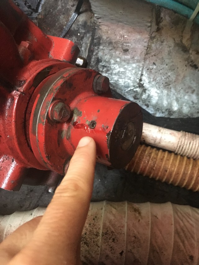
And, at the end, we have a key that fits in a slot on the prop shaft and helps the shaft grab and turn the coupling (in addition to a set screw and two bolts on the coupling that tighten down onto the prop shaft.  All fascinating stuff, I can assure you.  But, this stupid little key.

My God, the hours Phillip and I have spent dicking around with this key.  The thing would not stay in.  I can’t tell you how many times we have spent watching it wiggle out, sometimes halfway, other times entirely and we would have to fish around in our super clean bilge to find it, all to then hammer it back in with some Loc-tite and hope for the best.  It seems like such a terrible design.  Eventually we watched as the prop shaft itself began to—much like the key had—inch forward toward the bow of the boat and actually protrude a quarter-to-half inch in front of the coupling.  Those were good times.  And, I’m saving for you the story of what happened when the shaft creeped too far forward.  My point in all of this is to hopefully get you chuckling as much as we were when we finally realized what our amazing boat was trying to tell us with all of this key business.  “My coupling is loose!” she was screaming.  Poor boat.  She’s such a trooper when it comes to us, I tell you.  While the two bolts that tighten the coupling down onto the shaft had seizing wire on them, which is why we did not suspect they could loosen, we have learned anything that rattles on a boat can loosen (and wire can stretch!).  After we finally tightened the bolts on the coupling back down, the key hasn’t given us any further trouble.  But!  We’re thinking about having a new key machined that has a hole for a seizing wire so we can prevent any further “rattle out” issues in the future.  Rattle is real, people.  We’re taking measures!

Project No. 3: Some Westie Love!

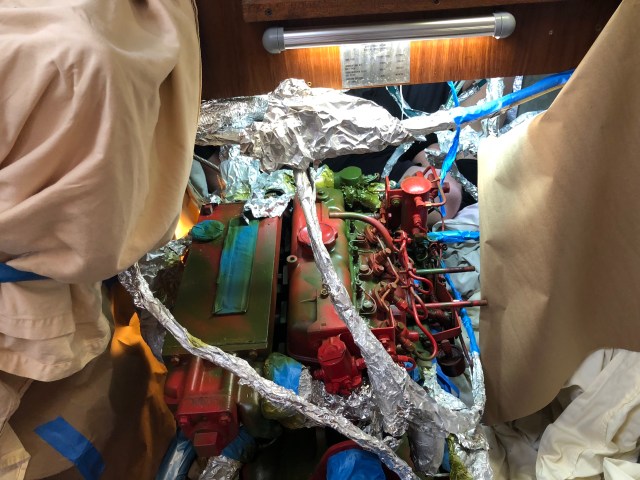
Boy does he deserve it.  “Westie” our 27A Westerbeke engine in the boat.  He’s been performing like a champ.

While we try to take very good care of him, always looking for leaks, tightening screws and bolts that rattle loose, keeping a very close eye on his coolant system, and changing the oil every 50-75 hours, Westie is getting up there.  He is the original 1985 engine on the boat with about 3,600 engine hours on him.  Plenty of life left for sure, but we do need to replace the exhaust elbow that goes to the manifold and the manifold gasket, give him a super scrub down (knocking off the flaking rust) and perhaps re-paint him and reinforce his stringers as they have spread and deteriorated a bit with water leaks (particularly on the starboard side under the water pump).

We will probably also drain the coolant system and change out the coolant and replace the gaskets around the thermostat as those tend to leak often.

Project No. 4: Forestay Maintenance

As many of you are aware, we replaced our original rod rigging with universal 5/16 wire rigging when we spent three months in the shipyard back in 2016 re-building our stringers (and doing a hundred other things).  Those were good times.  Videos for you here if you haven’t seen them (Raising the New Rig, Part One and Two).


Brandon said we deserved a “Boat Yard 101” training certificate when we splashed back because that was an absolute hard-core crash-course in boat maintenance and repair.  But, while it definitely sucked finding out the very important stringers under our mast were rotten and that it was going to cost several thousands to fix, those three months (and all the money) we spent in the yard in 2016 was the absolute best thing we could have done as boat owners.  There is no way we could have learned as much as we did from dedicated, knowledgeable boat repairman, craftsmen, experts, had we not spent that time side-by-side with Brandon and his crew at the shipyard.  So, we don’t regret it.  Ever.  And, it was time to replace the rigging anyway, so the timing actually worked out.

But, although our rigging is new (or, better yet, because it is new) during the course of our sailing the past two years, it has stretched.  Phillip and I noticed a little looseness in our forestay that caused it to (for lack of a better word) “warble” while we are furling the headstay, particularly our larger 135 genny, and particularly during the last 5-6 rolls of the drum.  So, we contacted Rick over at Zern Rigging and his guys came out to check our forestay tension.  While one of his main guys, DJ (we love you!) inspected it and said our forestay was actually tighter than most, he found we could afford a bit more tension so he and his guys tightened it up for us.

He also noticed immediately the grinding and difficulty in turning our furling drum (something Phillip and I have noticed for a while but figured it might have to do with the looseness of the stay).  DJ, however, explained that it would be easy for us, and quite prudent, to re-build the furling drum and replace the bearings inside as they just age and wear over time with salt and dirt build-up in there.  So, Phillip and I will plan a day while we’re in the shipyard to do that as well and I know that will work wonders when we’re furling in heavy (or any, really) winds.

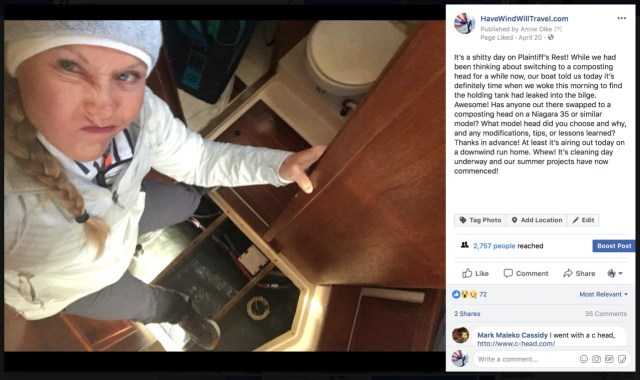
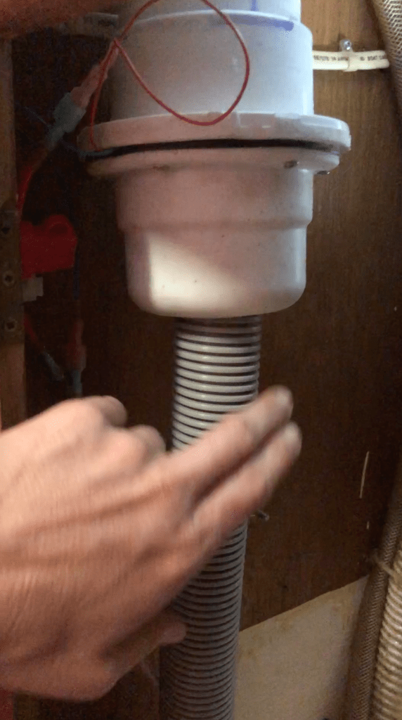
Project No. 5: Swap to a Composting Head?

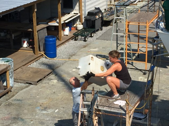
We’re hoping to.  At least I’m hoping to.  We are definitely keen on the idea of gaining the additional storage space where our 25-gallon “turd tank” currently resides under the v-berth and the theoretical convenience of no longer having to pump out or worry about holding tank leaks (been there, done that, gross!).

Phillip, however, is a little skeptical about the size and fit of a composting head in our rather small (and awkwardly-shaped) head compartment, as well as the comfort of sitting on and using a head so tall.  We’ve done a lot of research and talked to many boat owners who have switched to a composting head and have heard really awesome pros (like the ones I mentioned above) and the ease of dumping and cleaning the unit, no smell, etc. with just a few cons: the inability for urine to drain when on a particular heel, overflowing of the urine bin (if you don’t monitor it closely enough) and, to reinforce Phillip’s fear, the size and “comfort” of it.  Overall, we are on board if a composting head will comfortably fit, but our floor space in the head is very small and triangular-shaped.  I have been going back and forth with the Airhead guys (we believe they offer the right balance of look and fit that we want) and they actually drew a pretty to-scale CAD drawing for me showing how the head might fit (cocked slightly at an angle) and we will likely have to build a small shelf to support the urine bin.


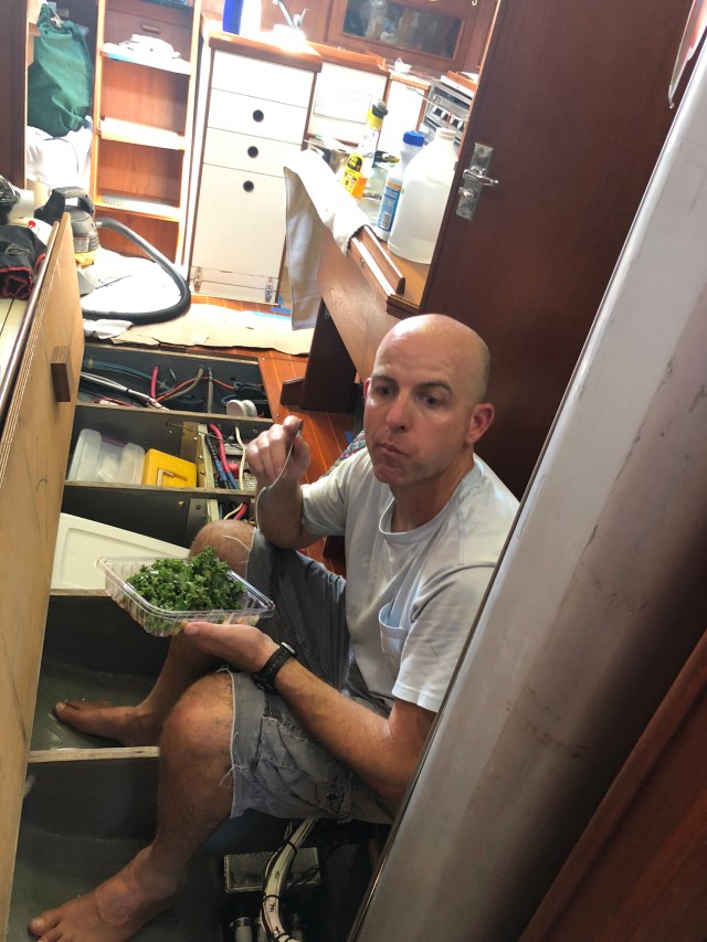
A friend of ours (you recall Phil who bought his first live aboard sailboat, a 1992 Catalina 28 which we helped him deliver last year) recently switched to a composting head so we’ve been learning a lot from him (always good to have a boat buddy make all the disgusting mistakes first, right? ; ) and he let us borrow his head to get a feel for whether it is going to fit in our boat.

It’s going to be a game of Tetris for sure, but I would really like to make this change this summer so I hope it works out.  Phillip has put this item exclusively on my list.  We’ll see how Boat Project Annie does.  Things might get shitty … : )

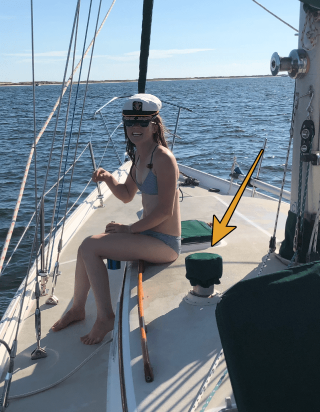
Project No. 6: The AC Inlet

The “AC Power” on the list.  We honestly had so many projects piling up, I forgot what this one was and had to ask Phillip.  I was worried we were going to have to re-wire our AC power system on the boat or something equally major that Boat Project Annie had decided to selectively forget because she knew it was going to be financially and physically painful.  Thankfully, it’s not too bad.  On our boat, we are always chasing leaks.  All.  Ways.  And, we believe we’re getting some water in from behind the AC power inlet on the outside of the cockpit on the starboard side.

Phillip tells me it looks like a “mangled rat’s nest” in the back all gooped up with silicone and other adhesives.  So, we’ll be popping that out and re-bedding it anew with butyl.

Project No. 7: Re-Bedding Stanchion Posts

While we’re on re-bedding (which it seems we are always doing).  We’ve got a few stanchion posts that are looking a little red around the bed.  Once we start to see rust streaks leaking out around the base, that’s a sure sign that puppy is leaking.  We’ve re-bed approximately six of the ten on the boat, so this will be another 2-3 and will hopefully seal those up for the next 2-3 years.  I can’t stand having unknown leak sources on the boat!  We’ll keep hunting and re-bedding till we have a dry bilge darnit!  Boat Project Annie is no quitter!

Project No. 8: Jib Sheet Turning Blocks 

Our previous owner (Jack, you fantastic boat-owner you!) re-routed the sheets for the headsail to come through a set of blocks mounted on a stainless steel plate to improve his ability to trim and tack the sail single-handed.  If you recall, our previous owner used to single-hand our boat in the Mackinac race.  Pretty awesome, right?  Our boat has such a cool history.  We are very pleased with the upgrades he made, this being one, but over time the bearings in the blocks for the genny sheets have failed and we need to have these blocks and their brake levers re-built.

We’ve been very pleased with the products we have ordered previously from Garhauer so we will probably send them a photo or the block itself to allow them to rebuild blocks for us.

Project No. 9: The Fridge??

Hmmpffh.  What to say here.  Honestly, we’re not quite sure yet what we’re going to do here, if anything.  Bottom line is our fridge is original to the boat, which means it’s now thirty-three years old and operates on an antiquated Freon system with inadequate insulation.

We’ve had the Freon refilled and we’ve spent some awesome Saturdays wiggling ourselves into that torture chamber squirting Great Stuff around the seams to try and improve the fridge’s insulation and ability to hold temp.

The fridge, particularly in the hot summer season, is easily our biggest power suck while on anchor.  We’re going to debate dropping in a new Freon fridge this summer or upgrading to a more efficient, more modern model that fits in our boat.  Stay tuned.

Project No. 10: Switching to LEDs

 This has been an on-going project, but one we want to continue pursuing until we have converted all of the lights on the boat to LED.  We swapped out a few of our reading lamps and fluorescent lights to LED before we left for the Bahamas and we were thrilled with the minimal output.

Think 0.1 amps an hour to light the boat.  Ummm … yes please?  So, we’ll be ordering and installing LED lights throughout and adding more red options where we can for better lighting options during night passages.

Project No. 11: Canvas Work!

If our time in the Bahamas during December and January taught us one thing, it’s we do not like to be wet, drizzly, and cold on our boat.  Thankfully, we were not, mostly because we spent those wet, chilly, super-windy days toasty warm in our wetsuits kite-surfing!  Heck yeah!

But, it did show us that the more comfortable cruisers were the ones who still had a warm, dry “living room” they could enjoy despite the wet bitter weather.  They just had to zip up their enclosures in the cockpit and *bam* it was a toasty day on the boat.  While we may not use them often, Phillip and I decided when you need them, you really need them, so we’re going to get a quote and consider having a full enclosure for our cockpit made so, on those occasional cold, wet days either on the hook or especially on passage, we can zip up our cockpit and stay toasty!  We’ve already put in a request for a quote from our trusty local canvas guy, Tony with Coastal Canvas, for a complete enclosure (which we are sure will run us a couple thousand, if not more …. but it is what it is) as well as having him fix some of the snaps on our hatch covers that have ripped off.

Project No. 12: BOTTOM JOB!

And, of course, what do you always do when you haul out?  That’s right, you got it!  Unfortunately we had to scramble and pull of a bit of an emergency haul-out last October for Nate, we feel incredibly fortunate, however, that Nate was just a tropical storm.  Do NOT ask me how I’m feeling about this coming season.  Makes my stomach turn … But, it was a very good hurricane prep drill for us (thankfully just a drill) and also a chance to scrub the bottom, scrape off a few obstinate barnacles, and slap a few coats of bottom paint on for the cruising season, and we plan to do the same when we haul out this summer.  A bottom job has to be my absolute favorite job on the boat, you?  ; )

We may throw in a little buff job, too, while we’re there.  She always looks so pretty when she’s all shined up!

Let’s see … what else.  That’s quite a bit.  You guys are going to have a mighty fine Schadenfreude feeling watching us work our tails off this summer making our beautiful boat even more comfortable and getting her ready for more cruising this coming season.  While all plans are written in sand at low tide, the vague plan is to go back to the Bahamas and spend our time really enjoying the Exumas and then maybe heading south toward Grenada to keep the boat there next season.  We will see.  Either way, you know we’ll find a dozen other boat projects to add to the list once we get in there and that we will share with you and conquer.


It’s a boat, right?!  Broke Or About To.  But that’s why we love her!