Hello crew! This is the final video from our time in the shipyard with Perdido Sailor in 2018. I know many of you have been very curious about our swap from a manual to a composting head, and I wanted to share with you the install process in detail. The ventilation system turned out to be the trickiest part (mainly because we wanted to utilize old, obsolete systems to hide as much of it as we could for aesthetic results). But, other than removing the … smelly items, this was really a rather simple install, one I was able to handle primarily on my own while Phillip was tackling the rudder post reinforcement and other projects, and one we are very pleased with.
Phillip and I have been weekend cruising for about six months now using the composting head and have found it to be a wonderful new addition to our life goal of keeping things simple. There is no more pumping after each flush, no more pumping-out at the dock, no more head smell in our boat, no more sloshing (could bust a seam any day) turd tank, and we’ve opened up plenty of new, now much more freshly-smelling lockers for storage. Oh, and we closed a thru-hull (the one for the macerator). So, we are down to only four thru-hulls now on our boat and thrilled about it. I told you our motto: K.I.S.S. If any of you are considering changing to a composting head, Phillip and I highly recommend it. I can tell you this: We haven’t heard of a single sailor going from composting BACK TO a manual head. That should tell you something.
As mentioned in the video, here is the link to the detailed blog post I put together laying out all of our research and reasons for swapping to a composting head: https://havewindwilltravel.com/2018/09/15/shipyard-project-no-6-swap-to-a-composting-airhead/. This includes the pros and cons we found and the rationale behind our decision to go with an Airhead, versus the Nature’s Head or C-head, and links to helpful articles, like this one from RV Lifestyle, that helped to educate us and inform our decision. So, feel free to peruse that helpful source before you watch the install if you would like to know more about our decision.
Then dive into this fun shipyard project video! The composting head has been a fantastic live-aboard lifestyle upgrade for us.
If you have any questions about our composting head, feel free to shoot them our way via HaveWindWillTravel. Enjoy the show!
As promised in the video: a link to the Squatty Potty unicorn commercial (hilarious). You’re welcome ; ).
And, a link to buy the Coco Bliss coco pith bricks for the composting head (which is roughly $4/brick and each brick lasts 3-4 weeks, we’re told, for live aboard cruisers).
Also, for my “strictly blog” followers, you actually get TWO videos this week. I realized when I shared our “Six Years Sailing at HaveWindWillTravel” recently on YouTube and Facebook that I forgot to share it as a blog post to my email-only followers. So, HERE YOU GO! A very fun six-year video re-cap in the new “Our Journey” tab on the website for you as well below. Enjoy both shows!
And you thought you were going to get to paint the engine today. Silly you! I thought I would give you guys a flavor of just how frustrating some of these boat projects can often be. If Phillip and I could just wake up, list one thing we wanted to accomplish on the boat that day, and actually be able to do it—just by sheer will—we’d be some might happy boat-owners. But, no matter your will power or persistence, what you are able to get done each day on the boat is dictated entirely by what the boat has in store for you. What’s hiding inside that project? Maybe it’s hidden deck rot. Maybe it’s a thirty-year bolt that’s bonded for life. Maybe it’s a piece that breaks upon removal. A bad design. Faulty wiring. Failing parts. Only the boat knows. And she will only tell you once you roll up your sleeves and get your hands in there.
Get in there people!
Our goal that particular day was to do exactly what you all said you wanted to see: start the engine paint project. All that stood in the way of that lofty goal was aligning the engine first. Typically that’s not too bad of a job. A couple of hours turning bolts and checking with feeler gauges. “No problem,” we thought. “We’ll be painting by noon.”
The boat had other plans. This was one of those surprise projects we hadn’t planned for. Projects beget projects …
You see, it’s not often a boat owner aligns his engine. I would imagine some never find the need to do it during the course of their ownership. But, anytime you remove the prop and re-insert it, you have to realign the engine to within the tiniest thousands of degrees. To be such a rugged, hearty engine, it does have a delicate side. Or so I’m learning.
I’ll be honest I did not know at first what this is. Do you?
It is an engine mount. And, while that title seems totally self-explanatory (“Ahh, they’re used to mount the engine to the boat”) I still did not know precisely what they did. Turns out, they are adjustable. These are precisely how you align the engine. You adjust the engine mounts with many tedious quarter turns to align the engine so the prop has a perfect straight shot to the transmission. As many of you have noticed from our photos, some crazy nut put our engine in backwards. And, don’t worry, I’ve heard all the jokes: “You can only go forward in reverse!” They are rather funny, but with this set-up we have two engine mounts on the forward side of the engine—one on starboard and one on port—and a single engine mount in the center of the cradle on the aft side of the engine.
You can see the engine mount here on starboard in the far left corner of the photo:
In the back, we have a cradle that supports the engine with a mount in the center:
I’ll bet you can imagine engine mounts that have been sitting undisturbed for some time don’t like it when you start shoving a wrench around their neck and trying to twist them. They respond like Oscar the Grouch. Much like the one stubborn bolt on our steering quadrant, we had one engine mount that simply would not let go. And, of course! (Because this is how the Boat Gods show they really love you!) Luckily we had engine mount replacements for the two forward mounts, which were still serviceable but pretty far gone, the one mount we did not have a replacement for was the one that was giving us trouble. The Aft Grouch!
Shane with Perdido Sailor tried many times to get her to budge, but she was bonded for good. So, we were forced to order a new mount from Westerbeke (which put us behind another four days on aligning the engine). Now, are you starting to feel me on the boat project frustration? But we were trying to keep the optimism.
“No problem,” we thought. “Just a small delay.” But, when Shane started to remove the engine from the stringers and raise it up on blocks so we could install the new mounts when we had all three, this happened:
Another rotten stringer! I mean …
Shane was actually reluctant to tell me because he knew what we had gone through the last time we found rotten stringers on our boat. I guess if you want to ever consider yourself lucky when you’re facing what may seem like a very bad boat problem, take comfort in that moment knowing if you ever face that problem again, you’ll know exactly how to solve it. The easiest project to do on the boat is one you’ve done before. Because you already know all the mistakes not to make this time around! When Shane asked me if I wanted him and his guys to get on the rotten engine stringer repair, I said: “Nope. I’ve got this one.”
As many of you may recall, back in 2015, Phillip and I discovered the stringers under our mast step had been rotting for some time. Enough so that the mast was crushing its way down into the boat with a visible bump showing in the stringer just under the mast step. This is what launched our extensive “Hard Times on the Hard” season of footage in the shipyard when we spent three months on the hill repairing our rotten stringers, replacing the rigging, and doing about a thousand other things while we were there. That stay at the yard is what easily prepared us for this comparatively short period on the hill (only 4.5 weeks this time, as opposed to 3 months back in 2016).
Russ with Perdido Sailor and I worked side-by-side for a solid week carving all of the rot out of our stringers under the mast, cleaning and smoothing the work area, creating thick way-overbuilt coosa-board fillers and laying down 163 (yes, 163!) pieces of glass into the backbone of our boat. She’s now stronger than ever. If any of you have not yet seen that project, I put together a great montage video below for Brandon showcasing the repairs, or you can watch the detailed videos (Part One and Part Two) I created for our YouTube channel, or scroll through the photos below.
That was a … monster job. But one that we tackled alongside the guys at the yard. And, Phillip and I learned a great deal about structural repairs and fiberglass work while we did it. While it was definitely not fun or cheap, it was undeniably necessary to repair the boat and highly educational. And, it has started to pay for itself over time. Because you know who handled the repair of this rotten stringer portion under our engine?
Yours Truly.
While the guys at the yard were great to set me up with the right tools and supervision, it turned out to be a project I could totally handle on my own. (Which to be honest, just felt pretty fucking cool.) Once I started digging into the stringer, I found it, thankfully, was not rotted the entire way through—just a portion which, no surprise, laid right underneath our raw water pump.
Before we replaced our Sherwood pump with a Johnson a couple of years back, we had battled leaks from our raw water pump and rebuilt and replaced that Sherwood several times with still no luck. We put the Johnson pump in in 2017 and haven’t had a drop down there since. But, Sherwood had already done his damage. However, I was pleased to find it was just a small portion of the stringer.
I will say, just like our stringers under the mast step, these stringers under the engine were not glassed on top. This just baffles me. So, the vertical surface where water will probably sit and where bolts will likely be drilled into—that area—you’re not going to glass. Just the sides and leave the top as fresh, exposed wood? While I love our boat and most of the design features, these stringers left un-sealed and exposed on the top was just not a good idea. But, c’est la vie. I’ve said my peace. It is what it is. We had rot. I had to fix it.
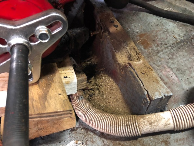
I showed the boys at the yard the amount of damaged wood I was able to pick and scrape away and I recommended I then cut a square portion out that we could replace with coosa inserts (much like we had done with the rotten stringers under our mast) and glass them in to build the stringer back up. Once I got the okay, I was set to work.
The hardest part of this job (and it was a very uncomfortable four-or-so hours for me squished and sweaty down in the engine room) was cutting out the square notch. There is just not a lot of room down there and the configuration forces some very hard angles of your body and wrists in order to accomplish square cuts. Plus, that marine plywood (when it is not compromised by rot) is some pretty dense stuff. It took a while with a Ryobi handheld blade and an air blade saw to get it knocked out, but I did it!
I then made templates (beginning first with construction paper) for the coosa inserts. I made Phillip cut the coosa (as payment for my services down in the engine room ; ) and they ended up being a very nice fit.
Our first step (again, much like we did with the mast step stringer inserts) was to “butter them up” as Brandon says, and glass them into place.
The next day I floated some of the gaps with 610 for a nice flush fit.
Then Brandon had the good idea to make a batch of resin and use a syringe to inject it down where the fiberglass walls of our stringers had started to pull away from the wood and then clamp them back to the wood for rigidity. This is the port stringer, which did not have rot, but we still needed to glue the fiberglass walls back into place:
Brandon also recommended we then lay a sheet of glass over everything over to seal it all up, allowing no more water intrusion.
I will say I got some props from the boys at the yard for handling this one on my own (and on my own time, so my own dime). I was quite pleased, as well, with how it turned out.
Shane helped us to cut and lay glass on the other stringer as well, just for added measure.
It truly is amazing he fits down there, but I can’t tell you how many times he went up and down the ladder and squeezed himself down there to do hours upon hours of work. “Think small thoughts,” he was say, jokingly, as he made his way down.
And, very much Brandon-style, Brandon recommended (while we already in there glassing) to go ahead and add two extra supports on the front of the engine near the transmission to help keep Westie extra secure. Do any of you know what these support beams are called?
Gussets!
I was learning something new everyday. And, the “rounded corners” you make with resin and 406 (because fiberglass does not like 90-degree angles) are called fillets. I’ll spare you the crazy conversation Shane and I had him trying to explain to me how to make fillets for the gussets. I was a lost cause at first, but the boys stuck with me and dumbed things down a bit so I could pick up what they were putting down and *voila!* It was totally worth it!
We also painted the entire area around and under the engine, including the stringers, so everything would be pristine for the re-mount. I knew a fresh coat of Bilgekote grey would make the perfect back-drop for our bright-and-shiny Westie-red!
Let’s talk about our rudder. While Phillip and I are quite pleased with the majority of the systems on our boat and their original design, this was one where—if we could have been there at the factory in Ontario when the Hinterhoeller crew was putting our boat together—we would have asked them to make a slight modification to this rudder design. Here are the components of our rudder:
It is a very sturdy, yet light-weight, high-performance rudder, with a keyway to grip the steering quadrant and a very hearty nut on the cockpit floor that turns and locks down with set screws to hold the rudder tight, the only issue we had had with it is where the rudder post penetrates the cockpit floor. If you can imagine how much pressure is put on our rudder when we are steering down waves in a gnarly sea state, that pressure is magnified at the fulcrum point where the rudder fits through the cockpit floor. And the only thing holding it firm there is a rudder post cap secured with three 1/4” bolts. Here is a photo of the rudder post cap with the nut and plastic bushing, followed by one (with the plastic bushing and nut removed) and the top of the rudder post dropped down a few inches during our rudder drop.
As many of you die-hard HaveWind followers might recall, we first noticed a problem with this rudder post design during our offshore beat to windward when we sailed to Cuba in 2016.
Yep. That’s the one. Try to imagine how much pressure is on the rudder in that photo and how much of that was being translated to those three little bolts on the cockpit floor. It was enough to cause our rudder post to start moving side to side, athwartship. Which, once we saw it, immediately caused Phillip and I to go upside down in the lazarettes trying to stop it.
This is what we found when we got down there:
Just three bolts (the third, on port, is concealed behind the rudder post) with initially only one washer and one nut on each. Adding the additional two is what Phillip and I were doing down in the lazarettes on our way to Cuba. And, while the additional nuts did stop the majority of the athwartship movement of the rudder post on the cockpit floor during that passage, you can see in the photo above where we have tightened them so much they are literally starting to crush the cockpit floor. This is what really worried us: such a small compromised area holding such a critical, heavy, and load-bearing component of our boat.
We knew when we got back from Cuba, we wanted to take some measures to reinforce this area before we sailed to the Bahamas. Our initial reinforcement plan—without having to drop the rudder—was to add large stainless steel flat fender washers to help spread the load of those three bolts. Our buddy Brandon with Perdido Sailor (with whom we usually haul-out) helped us grind the washers down to fit around the cap that sits in the cockpit floor.
Annie making an immaculate cardboard template of the area on the engine room ceiling around the rudder post.
We then used the template to make custom washers to fit around the bolts that go through the rudder post cap on the cockpit floor.
We knew this would be a temporary fix for the season, though, and that, when we got back from the Bahamas and hauled out the following year, we wanted to drop the rudder and really do this project right. And, we knew we would be hauling out again with Brandon at Perdido Sailor because his work is exceptional and he and his guys are willing to allow us to tackle projects there ourselves while they teach, supervise, and rightfully pick on us … that’s shipyard culture. In researching how we were going to accomplish our rudder reinforcement, I mentioned in my Post-Bahamas Projects blog what we discovered when we talked to some fellow Niagara 35 owners through the Niagara 35 Owners Facebook Group. We found one Niagara owner, who was had just finished crossing the Atlantic, and was in the Azores at the time, not wanting to haul out and drop the rudder at the time, decided to add a very substantial backing plate around the top of the rudder post to help reinforce and secure it.
I guess you could call this a topping plate, since he mounted his on top of the cockpit floor. After discussing this at length, Phillip and I decided we wanted to mount our plate underneath the cockpit floor for cosmetic reasons. Either way, top or bottom, we knew a large plate mounted around this hole would help spread the very heavy load of the rudder and help reinforce the cockpit floor. We got with our buddy Mike, who helped us configure the initial custom-washer-fix and who is a talented machinist (and owner of a beautiful 1981 Tartan 37 – boat tour HERE! – you’re welcome! : ), about making a plate for the underside of our cockpit floor. Say “Hey!” to Mike!
And this is the wonderful piece Mike made for us!
Look at that smile. I mean, who wouldn’t be grinning from ear to ear knowing they’re about to have a tough-as-nails rudder rig-up on the boat. Heck yeah!
After measuring underneath the cockpit floor and assessing the sufficient space we had down there (the closest item to the rudder post is our rudder indicator on the port side), we decided on the following fix:
An8 x 8” stainless steel 1/4” reinforcement plate
After playing around with the plate down below in the engine room, we found sitting it in a “diamond” fashion with one corner toward the bow, one to the stern, one to starboard and one to port, would allow the plate to sit centered on the hole and not touch any other instruments on the engine room ceiling near the rudder post. Like this:
You’ll notice those holes on the cockpit floor by the binnacle base. Those are for the rudder post stops. I was in the process of re-bedding them when the plate came. We do a thousand things when we’re on the hard!
Here is the design, after the center hole in the plate was cut, mocked-up on the top of the cockpit floor:
While this fix (i.e., drilling the three necessary bolt holes through this plate and mounting it underneath the cockpit floor) seems like a pretty easy fix, Brandon spotted another issue when we were dropping and disassembling the rudder.
Pssst: This is why we love this guy and always trust him with any boat repair.
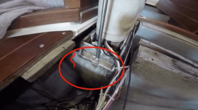
When we pulled the rudder cap from the cockpit floor this was the hole we found that was cut for our rudder post.
Does that look perfectly round to you? Hardly. That’s an amateur Annie cut right there! Not something we expected to find on our blue-water Niagara, but, as the boys at the yard said, our rudder install must have been done on a Friday shift, before a long weekend. Humans are just that. Humans. Someone at the Hinterhoeller facility didn’t really take their time making this cut. But, even if it was round, Brandon also found it was about a half inch too wide for our rudder post cap. Meaning, not only was the cap itself only secured with three 1/4” bolts, it also was not supported in this hole with solid 360-degree contact all the way around.
“We’re gonna fix that,” Brandon said, and he ingeniously came up with the idea to mount the rudder cap upside down (from the engine room ceiling up through the cockpit floor), so it would reveal the gap we needed to fill on the cockpit floor. This photo really highlights, too, the poorly-cut hole and the gap that we wanted to fill.
Brandon then advised us to coat the cap with TefGel (that way the 610 would not stick to it) and fill that wayward-cut gap with 610. That is what I am doing here:
Annie’s got her gun!
We then waited for the 610 to firm up enough to hold its shape (about four hours), then popped the rudder cap out and now found our hole in the cockpit floor for the rudder cap was a nice, snug fit, way more supportive than what was there previously.
This way, as Shane with Perdido Sailor explained, the hole for the rudder post cap, along with the cap and reinforcement plate will all “operate as a system” to hold the rudder secure in the hole, even with the tremendous amounts of pressure that are put on it when we are offshore.
After we sanded our 610 filling and smoothed everything up, we then bedded the rudder cap down with butyl. Love that stuff!
We mounted the plate underneath the floor with our three bolts, using our custom washers from last year’s temporary fix and secured it all with locking nuts. This is the complete rudder reinforcement fix:
Pretty schnazzy huh? As Phillip said to me: “Aren’t you going to sleep better when we’re underway offshore knowing this bad boy is holding everything together?”
Yes, yes I am.
And, added bonus for you Phillip fans out there. I snuck a video of him explaining to a boat neighbor of ours (ironically both in the slip and then at the shipyard as well!) how we discovered this problem and our thought-process in designing the reinforcement. Enjoy!
Phillip and I are both very grateful for the help and guidance shared through the Niagara 35 Owners groups, particularly the input from Larry Dickie, as well as our buddy Mike for the machine work, and the hard-working shipyard repairmen at Perdido Sailor, who helped us engineer and accomplish this feat. We hope sharing this fix helps some of you analyze and upgrade your own rudder systems. As always, if you have any questions about what we did here or just want to talk about it more, feel free to comment or share! Happy sailing folks!
And, don’t worry … we’ve got plenty more project posts to come this summer. Here’s the (short) list! The ones with an “A” beside them are my babies!
That’s right. It’s our very own s/v Plaintiff’s Rest, post re-rig, re-fit and repairs. I will also show you each of the features on our boat that Phillip and I believe make it a great cruising vessel from engine access to batteries to the sump box and more. If any of you out there are boat-shopping right now, I hope this video will help you understand why we chose the boat we did and what features and systems you may want to look for in a good cruising boat. If there are any modifications or upgrades that you see in this video and want to know more about it, be sure to “search” (right hand tool bar on this page) for a post on it on the blog. I’ve done a write-up or video on just about everything. If you don’t find the info you are looking for, shoot me an email and I will be happy to answer as best I can. Happy Boat Shopping!